Hey guys,
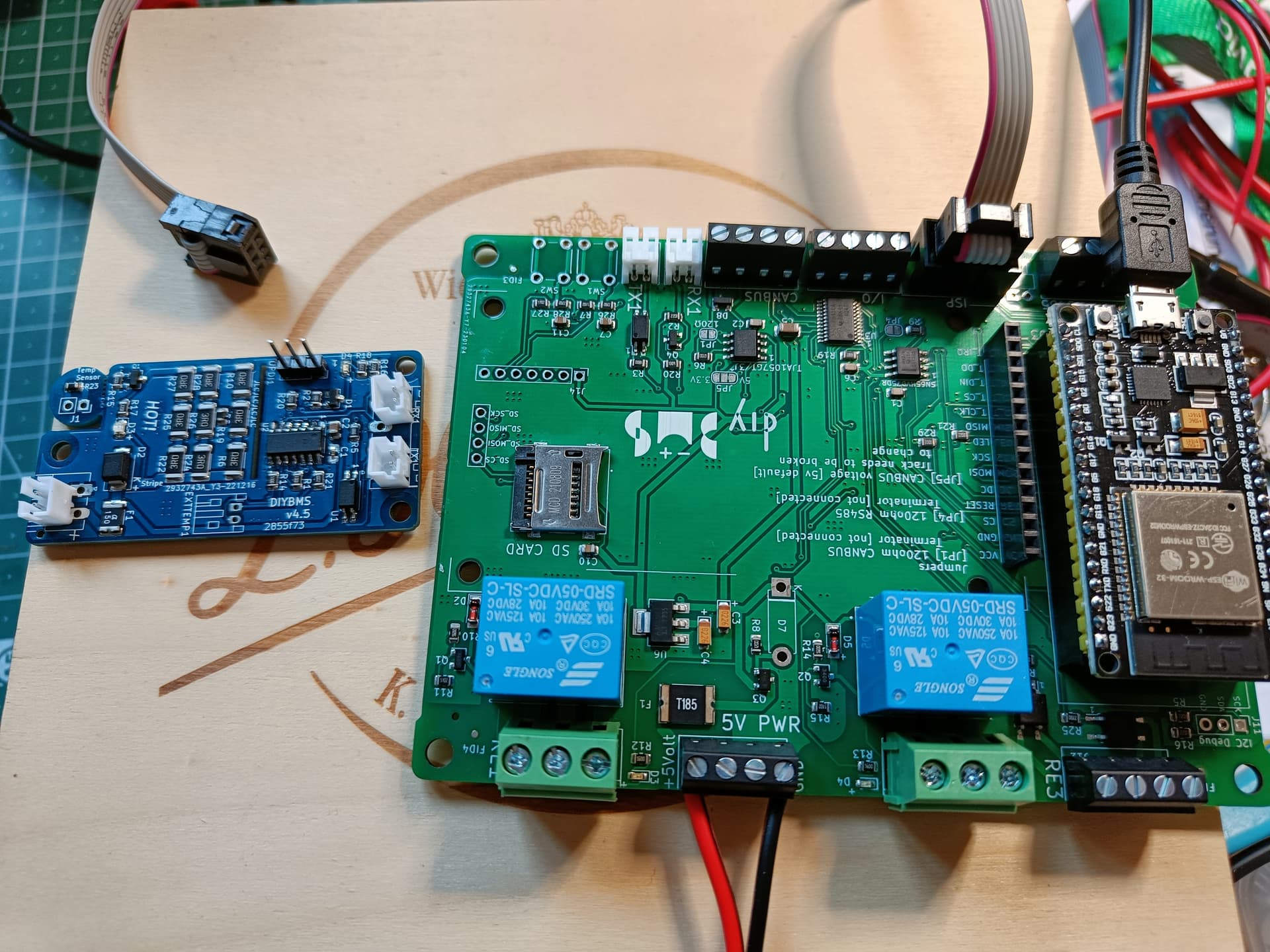
Just finished my controller and the first module
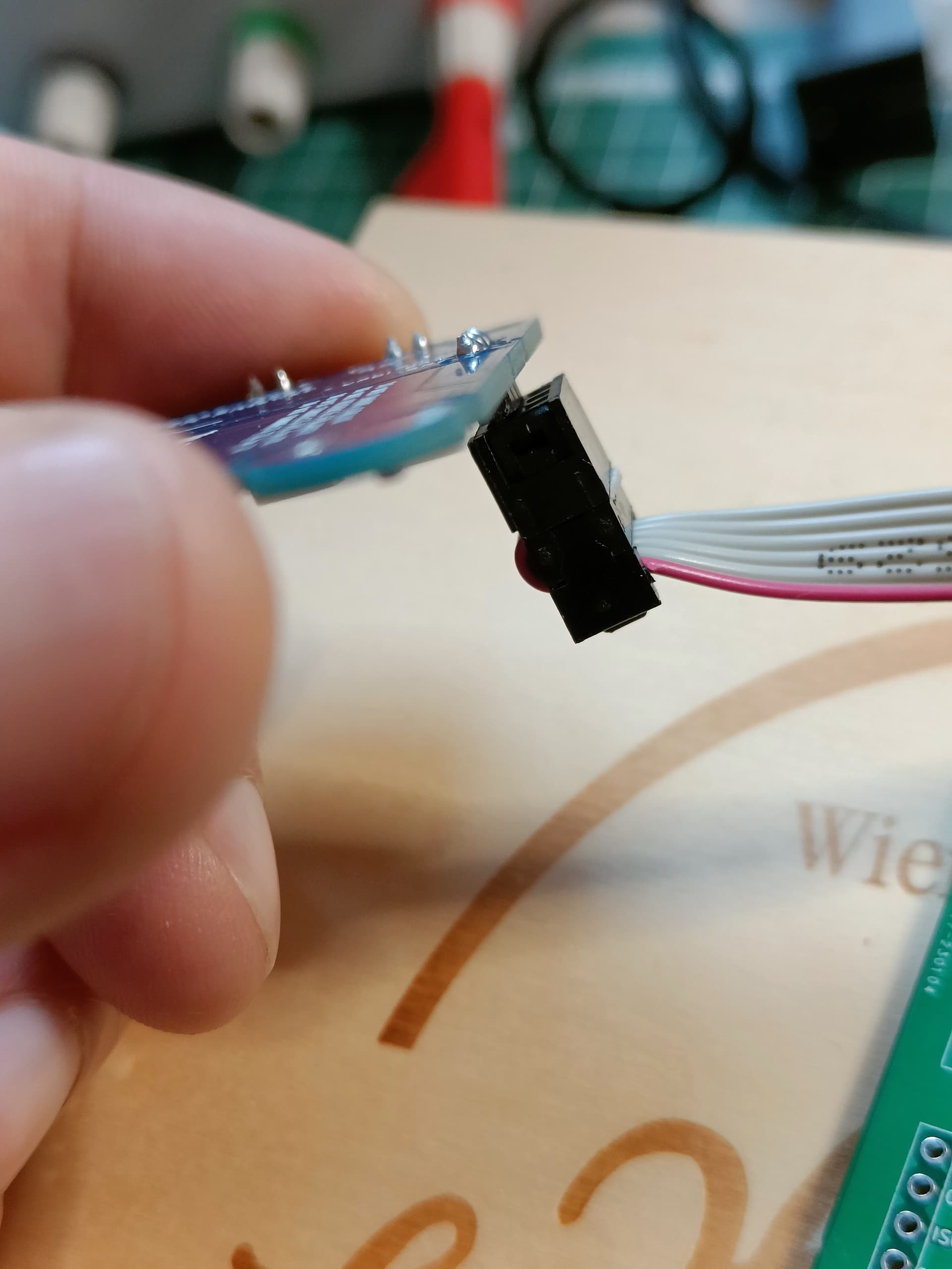
Now I plugged the 6 pin cable in one side and on the other side just the upper 3 pins ( with the notch)
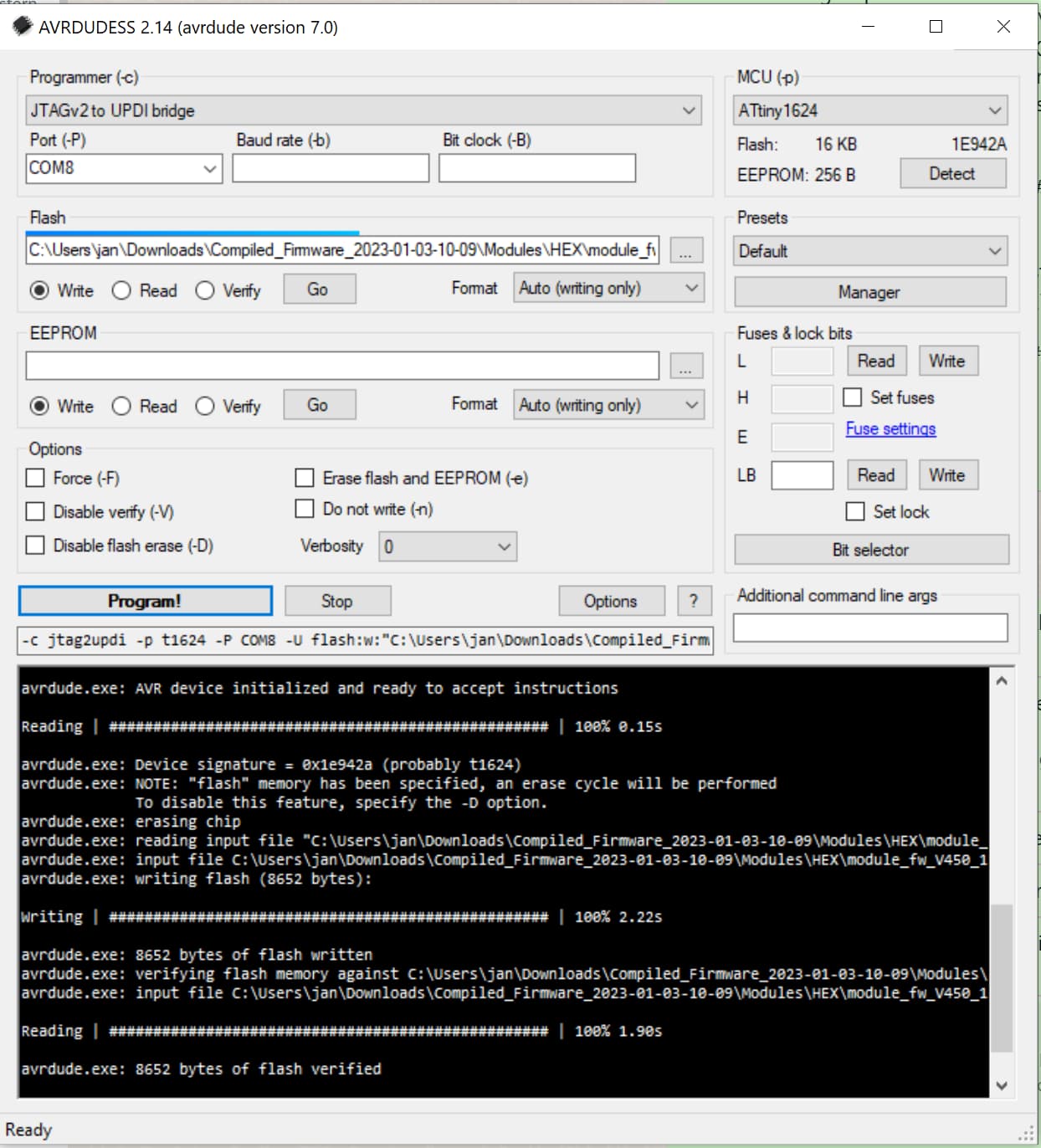
But when I try to flash them this error will appear.
Its V4.4 of the module with 6 pin connector.
But I think on 4.5 its still the same direction of +/- pole.
You get this message when the module does not answer.
E.g. there is no module at the other side of the cable.
Or you have no contact on a nessasary pin. Bad soldered.
The new Attiny1624 on the 4.5 controller needs a diffrend programming device.
So called UPDI programmer.
The Controller board is not capable to program the new controller chip.
Only the Attiny841.
So you won´t have success with the DIYBMS Controller…
Oh thanks,
I was wondering if there is any tutorial how to use the updi ?
I’ve never done that before…
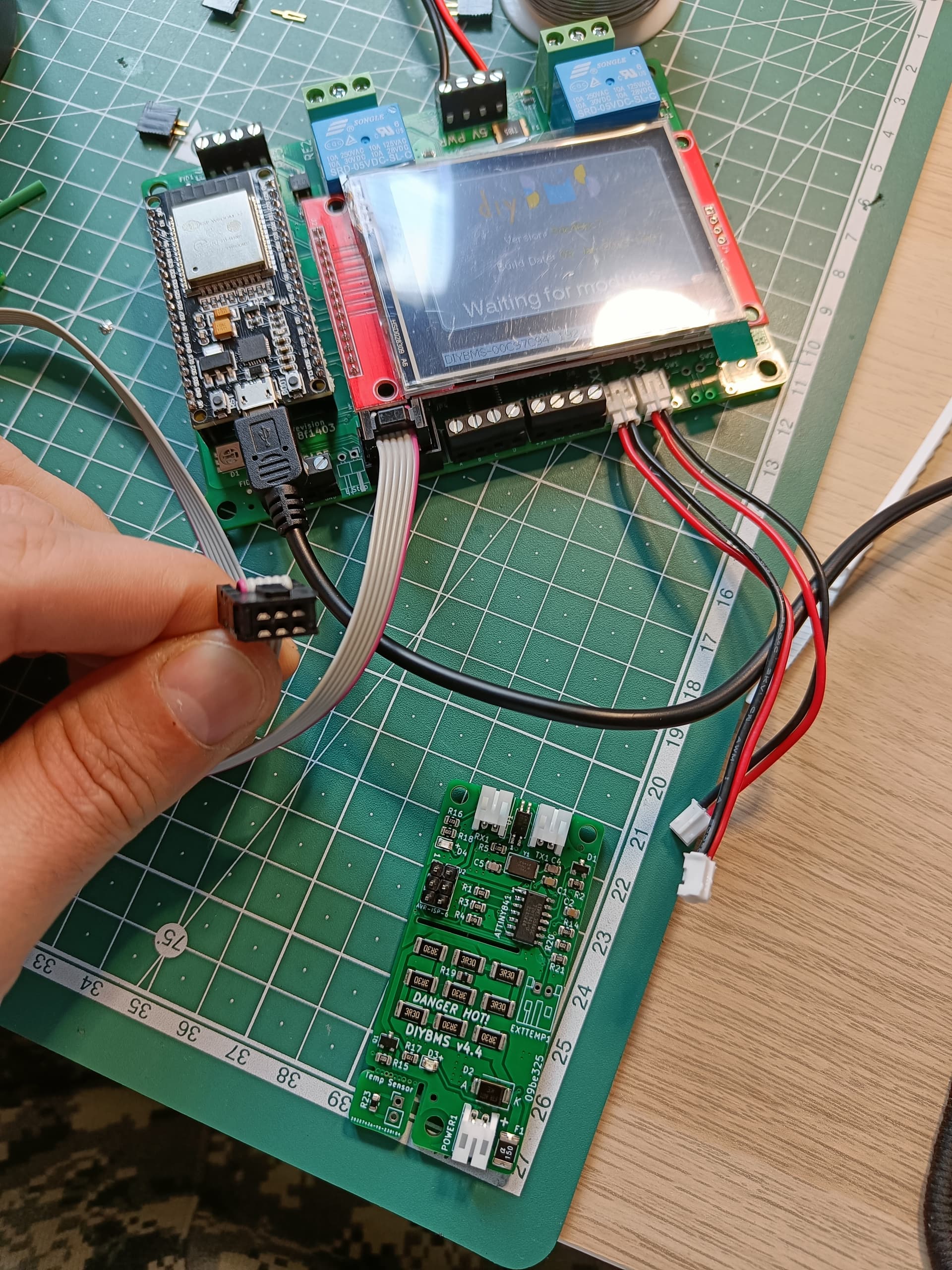
And sit here with the 4.50 modules without any software on it.
Look for the video of the shunt.
And read the github.
I also didnt know that the system has changed.
I changed to the new controller because it is easy to program the modules.
When this does not work anymore there is no advantage on the new controller for me.
For me it was not difficult to get 841. I ordered them via Alibaba in china.
Took only a few days.
And I have only 1.9f boards.
I agree, but unfortunately there is no UPDI programmer that will run on the ESP32 (I tried one and it failed miserably). Additionally the resistor is not present on the controller PCB to combine RX/TX.
The only reason Stuart changed this is because the ATTINY841 are becoming very hard to locate and the price has increased, the new ATTINY1614 is much cheaper and more readly avalaible, I am sure in due course someone will release a video on how to flash it.
I say again. I ordered the 841 in China and got it in a week.
Maybe the 16xx is an Euro cheaper.
But it is very uncomfortable to flash.
And the new Controller becomes partly obsolete.
for now. It should be feasible to have an adapter PCB of sorts that adds the missing resistor and a bit of time to sort out issues with the UPDI protocol.
I have the same problem, i dont know why. The controller program the module before, now always show the error code like you have on the picture. I’ve checked the pins, they’re in right orientation