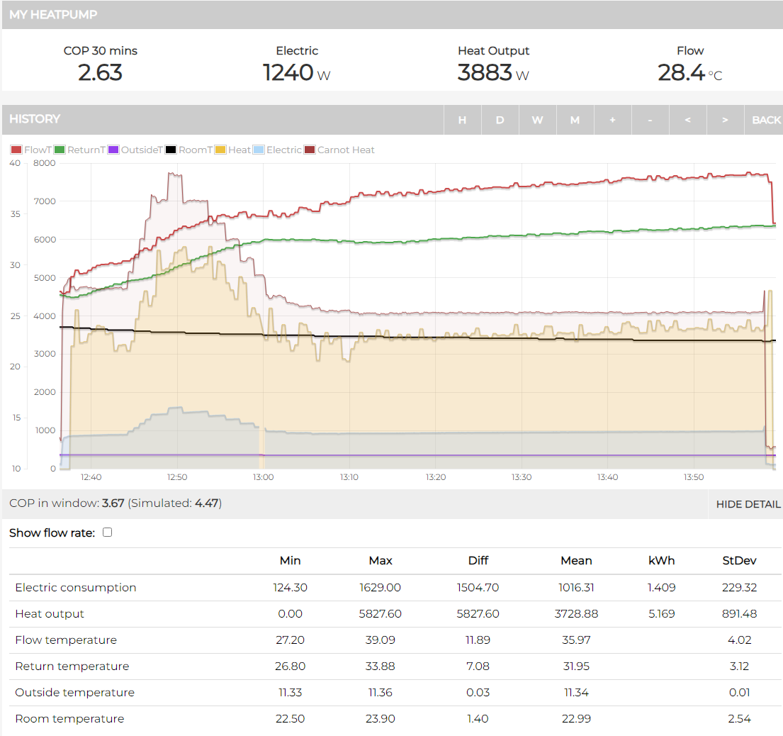
I feel that a lot of the inefficiency that I see comes from the initial phase of a heating cycle, once it has settled down it is pretty good but it takes a while, 90 minutes this morning. Overall though it was ok.
But after the initial heating cycle it just seems to go wrong. I can do what Tim has done, simulate the heat output using the carnot COP equation and it’s off unlike the morning when it had settled down.
I don’t know what is different from the morning for the rest of the day but it just doesn’t work as well.
I can’t bring myself to spend £1,200+ on fans that may or may not solve the problem. I’ll have to carry out electrical work and/or have cables and extension leads everywhere. I also have no idea how long they would last, not as long as a radiator I suspect. I can’t see how trying them on one radiator is going to give me an answer to my problem.
I think I just have to bite the bullet and buy radiators.
My total proposed radiators will have an output of 36,000kW at a delta t of 50c.
My rough calculations tell me they should be able to cope with the full minimum output of the heat pump at a delta t of 10c, that is a flow/return of 35c/30c and a room temperature of 22c.
I think you get about 13.5% of the output at a delta of 50c when the delta t is 10c (or 10% of the output that you would get at a delta t of 60c)
Here are some numbers from my system for comparison: 16,655 W of radiator output at +50 C, so 3,814 W at +15 C (23%). Minimum output from my 11 kW heat pump is 4 kW, so I run with a flow temperature a little above 35 C. Attempting to run lower results in lots of cycling. Measured heat loss of the house at -1C is around 5 kW.
I think the low COP at cycle start is just the energy needed to heat the flow and return and the pipes and radiators back up to the operating temperature. You do in fact get this back at the end of the cycle - you can see some minutes when the compressor is off but the heat out is still positive (infinite COP). SO we need to look at the full cycle COP.
I am not sure that Matts system had stabilized at 42c , especially when the outdoor temp rose to 12c where the ‘potential’ COP and min compressor speed output will have risen. It also looks as though it is switching off at 38c - is this because the setpoint has been lowered or modulation has lowered it? Or because the room thermostat switched it off? If the former then try setpoint = 44c. I think we have to find the system equilibrium as a first step.
Re the comment on defrost - it is highly unlikely that there is any frost on the unit. Mine does not show until 4c or lower and there would be no need for a system running at minimum to frost up at all at current temps…
As a guess it could be that some of the unused energy is making the compressor run hot and it’s tripping? As I say just a wild guess but there is still a sawtooth waveform in the flow temp so the rads are not ‘releasing’ all of the HP output. Let’s say they release 4kw when the HP could have produced 4.5kw with the same 900w compressor power. So it’s only using 800 watts of the 900 watts input, I guess that 100w has to go somewhere??
Your COP this morning when it was nearly stable was 3.98 from 7am to 10am. My quick estimate using the carnot formula suggest that this would rise to about 5.5 when you can lower the flow temp to 35c. That is the equilibrium level and not the overall level.
This is perfectly consistent with my system which produced a COP of 5.6 at 35c flow for a 3 hour stretch earlier this afternoon.
So we know your HP is working as it should and that the potential is there to get better.
@matt-drummer could you provide pictures of the heat meter and flow and return temperature sensor pockets by any chance? you may well have already done this and I’ve missed it? Do you have a volumiser? I note the description on your entry says no hydraulic separation, so no buffer or low loss header?
The pictures are there, I will find the post number but I think Vinny has just added them.
Post 71 and 96
I have no buffer tank or low loss header but I do have a 20 litre volumiser. It is just in series on the return to the heat pump and is little more than a really well insulated big piece of pipe.
It is the last thing before the magnetic filter, then through the heat meter and back to the heat pump, all in 28mm pipe
The flow from the heat meter goes through the t piece you provided as part of the kit and then into the three port valve that determines heating or DHW.
The only other part of the system is an expansion vessel.
There is nothing else. All the primary pipework is 28mm and the radiator pipework is some 22mm and the rest 15mm.
All my trvs are wide open.
I have checked the flow and return temperatures on every radiator and I have purchased a thermal imaging camera to make sure every radiator is actually flowing water.
They are and they all show about a 5c difference between flow and return however I measure them, I actually have four different instruments to do it with now (don’t ask!)
I listened to Marko and made sure there were no issues with radiator balancing.
The data from my OEM system agrees with my Daikin MMI, the OEM reports the same electricity use and a bit more heat production. I also have a CT clamp monitor on the heat pump total supply and that also agrees with the MMI and OEM.
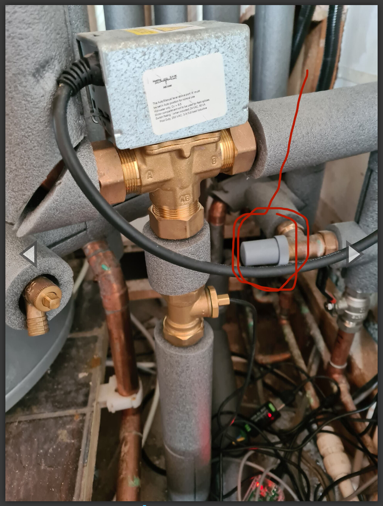
It looks like you have an auto bypass valve fitted. I have one of these, and I believe it’s unnecessary if you run an open circuit, or even have one rad with no TRV, I’m sure others can explain better.
If it’s not setting correctly it can cause issues. On advice I shut mine in completely so it won’t activate.
Might be nothing but worth checking on its setting, screw off the grey gap to check.
Edit: additionally I have just recalled its position close to the valve is also poor. If installed, it should be located at the further point in the circuit from the pump. Mine is installed in a similar position to yours, and early on was causing a short circuit under certain conditions.
Yes agree with @HydroSam, I have the same auto bypass valve fitted by Octopus. Try closing it fully ( noting current position to be able to put it back)
I promptly closed that down fully after they left! No issues…
The data I am publishing is basically from the same heat pump as yours, and is derived from:
ESPAltherma (M5StickC-Plus connected to X10, then posts over WiFi to Home Assistant, which in turn posts the data to Emoncms cloud service, and then input processes the heat delivered feed there)
And myenergi CT clamp (feeding data to home assistant and then again onto Emoncms cloud.)
It will be interesting to see if there is anything useful in comparison over the winter period with regards to accuracy etc.
If the auto by pass is fitted then I wouldn’t close it completely but set it so that it only opens when all the TRVs are closed (and any non TRVd rads) . There is a set up procedure for this on the Daikin. You will find that the pump trips below about 7 lpm as far as I can remember, so you want to set the bypass just above this trip point by trial and error. Although it is not ideal to be close to the pump I would imagine that the above procedure should take care of that as the Daikin will be running the pump at maximum in the test and so the pressure across the bypass will be at the highest it will ever see (the bypass is really a relief valve).
Just before anyone else says how bad their installation is - I found that my installers had a) duplicated my 22mm pipes to my HW tank with 28mm (really? the pressure drop across 10 m of 22mm is hardly an issue) and b) connected the flow and return of the original 22mm with a ball valve which they left fully open. A brilliant set up! So I bought and fitted a bypass and set it up as above.
The ESPAltherma doesn’t need HA. It uses JSON over MQTT so would probably integrate directly with EmonCMS, or any other MQTT-subscribing collator e.g. NodeRed, Python script turning it into CSV etc. I was actually an IT guy, and although I’m using HA at the moment, I have an extreme dislike of it.
If you were to run it at the same time as the OEM stuff, you would be doing the world at large a huge favour with your comparative stats!
I’m very interested in the ESPAltherma setup, but I’ve looked at the installation manual for my EDLA09D3V3 and I can’t see any connections marked X10 on the circuit/PCB diagrams.