I thought I pass this info on to those who might have a TED 1001 or 5000 MTU - you can buy the MTU for the 1001 with 200 amp cts still pretty cheap at $45 - and should be easy enough to pass the data to emoncms… though I have not tried that specifically http://www.theenergydetective.com/1001mtu.html
you can check out my old projects from long ago on 5000 MTU hacks-
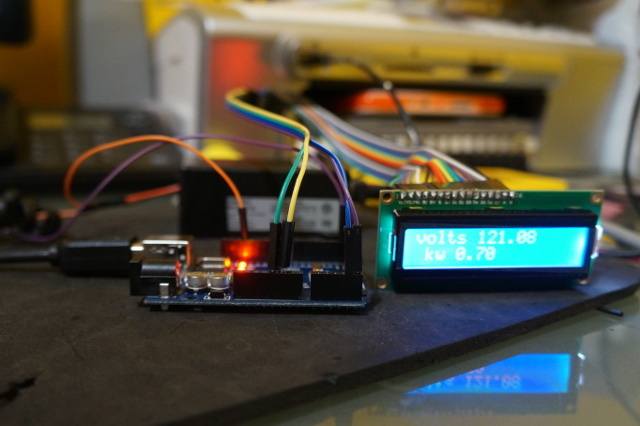
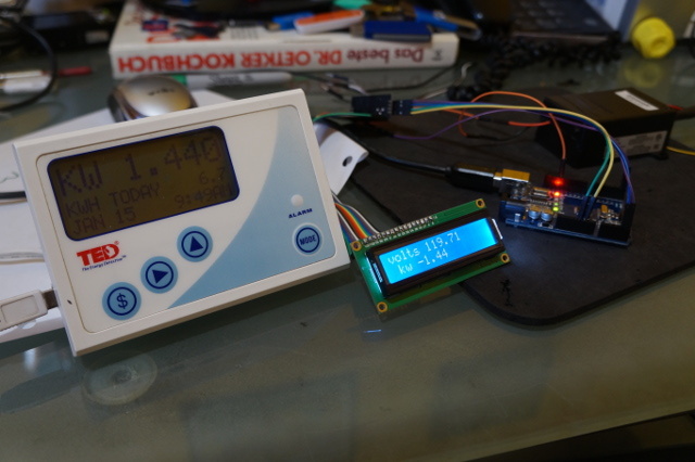
okay I had nothing to do this afternoon so i quickly threw together an ESP8266 sketch. it sends out a mqtt json format. every 1 second. it will display the voltage and power on the screen and at boot display the IP for 5 seconds
if you want higher accuracy just modify this line in the sketch ( it very accurate at even these low wattage I wish EMONtx was that accurate it easily accurate to <1 watt it down fall is it not very realtime it about 1-2 seconds off realtime as it averages data out over 1 second before it transmits data to the powerline encoder )
Pw =(power);
to
Pw =(power*1000); which converts it watts reading instead of kW and 0.64 kw becomes 638.24 watts
Hi there I forgot some important info to get this sketch to work with your device it has to know your MTU but you could also just remove the if statement for that if you can not figure out you inverted Hex of your MTU
void showGroupsOfBytes() {
    if ( receivedBytes[0]==0x1A )  { //inverted number of your MTU ie for 0x1A = mTU decimal = 229  and  hex = E5
    // if (numReceived < 9) {
    byte j = 0;
    byte k = 0;
    byte m = 0;
    byte r = 0;
    byte h = 0x1A;  //edit here too
     byte n = (0);
another way to get the number is with CUTECOM or what ever terminal program you use and modify your ted100 RDU like this:
cutting trace at pin 5 and then soldering a jumper to R20
this modification allows to to directly view the transmitted data from MTU unit ( actually all MTU connected to your system)
the Hex that is required comes after AA that is the start and end bit
example output from cutecom - you notice the aa then follows 1A that is your MTU its inverted value
00001080: aa 1a 85 ff ff ff 45 e4 94 02 f3 aa 1a 80 ff ff
00001090: ff f6 10 95 03 1a aa 1a 7b ff ff ff 9e fa 94 02
000010a0: 8e aa 1a 79 ff ff ff f6 10 95 03 21 aa 1a 76 ff
000010b0: ff ff 9e fa 94 02 93 aa 1a 74 ff ff ff 9e fa 94
000010c0: 02 95 aa 1a 70 ff ff ff 45 e4 94 03 08 aa 1a 6c
000010d0: ff ff ff 45 e4 94 03 0c aa 1a 63 ff ff ff 9e fa
000010e0: 94 02 a6 aa 1a 61 ff ff ff 45 e4 94 03 17 aa 1a
000010f0: 5e ff ff ff 45 e4 94 03 1a aa 1a 5c ff ff ff
another way to get it is use binary to hex an invert manually
example : MTU 229 = hex E5
hex to binary
e5 = 1110 0101
inverted
1110 0101 = 00011010
binary to hex
00011010 = 1A //insert this into the sketch
I figured well it is thread on TED1001 I might as well included an updated to include the for mention ted1001 RDU hack above. for those who have hacked their TED 1001 and wish to upgrade to emoncms for data logging. one of the advantages to hacking ted1001 RDU it can capture the data from several MTU units at once . the software that i included from my old ted project can do 3 ted MTU but more can be added explained in the readme
tedstart.pl -----is a simple watchdog for ted1a.pl
ted1a.pl ----is the packet decoding and MQTT send app . it also has quality control. for the Ted 1001 RDU. sometimes if the data stream becomes corrupt ( noisy powerlines) you need to reboot the ted1a.pl to correct the issue. or if it looses USB serial connect it need to relocate it again. after 22 bad or lost keys . the software will shut down and then automatically reboot the over all process is less then a couple seconds
simply install these 2 file to what ever device you have your ted 1001 RDU unit plugged into ie Raspberry/orange Pi , computer or router ( if you know how to install third party apps into your router ) then simple edit ted1a.pl with your network information and your devices MTU hex ID simple configure tedstart to run at boot
This project looks fantastic! Have you by chace ever messed around with the older 1001 MTUs? My 1001 RDU seems to have given up the ghost and I’d like to avoid buying a new system.
yes that what I have . but there are the older MTU and the newer MTU for the TED 1001 I only modified the newer one as for a couple years the TED 1001 was selling dirt cheap $20 so i bought a few to mess around with… they all had the 5000 MTU if you have the older one you probably have hunt out the the placement of the serial in/out to the main chip if i remember right it was pin 3/4 ( but I referenced the picture above it seams to be another pin I have to pull apart a mtu and see if i can get you the correct pin number as it is the second pin from the right is the one I am using on the bottom row ) maybe 13/14 are the pin numbers
then all you do is is one to ground and one to serial RX and load the software on the arduino or esp and a way you go…
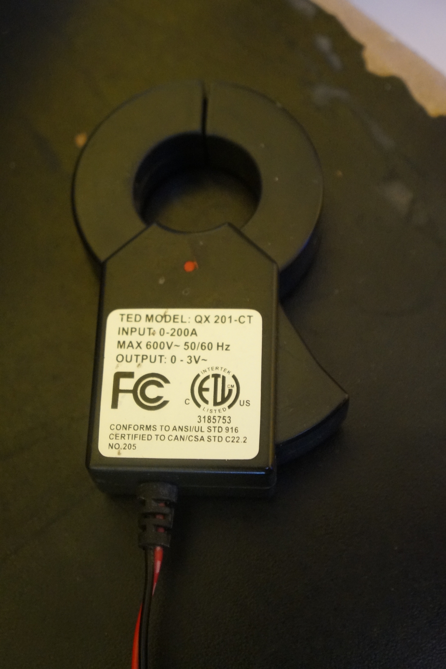
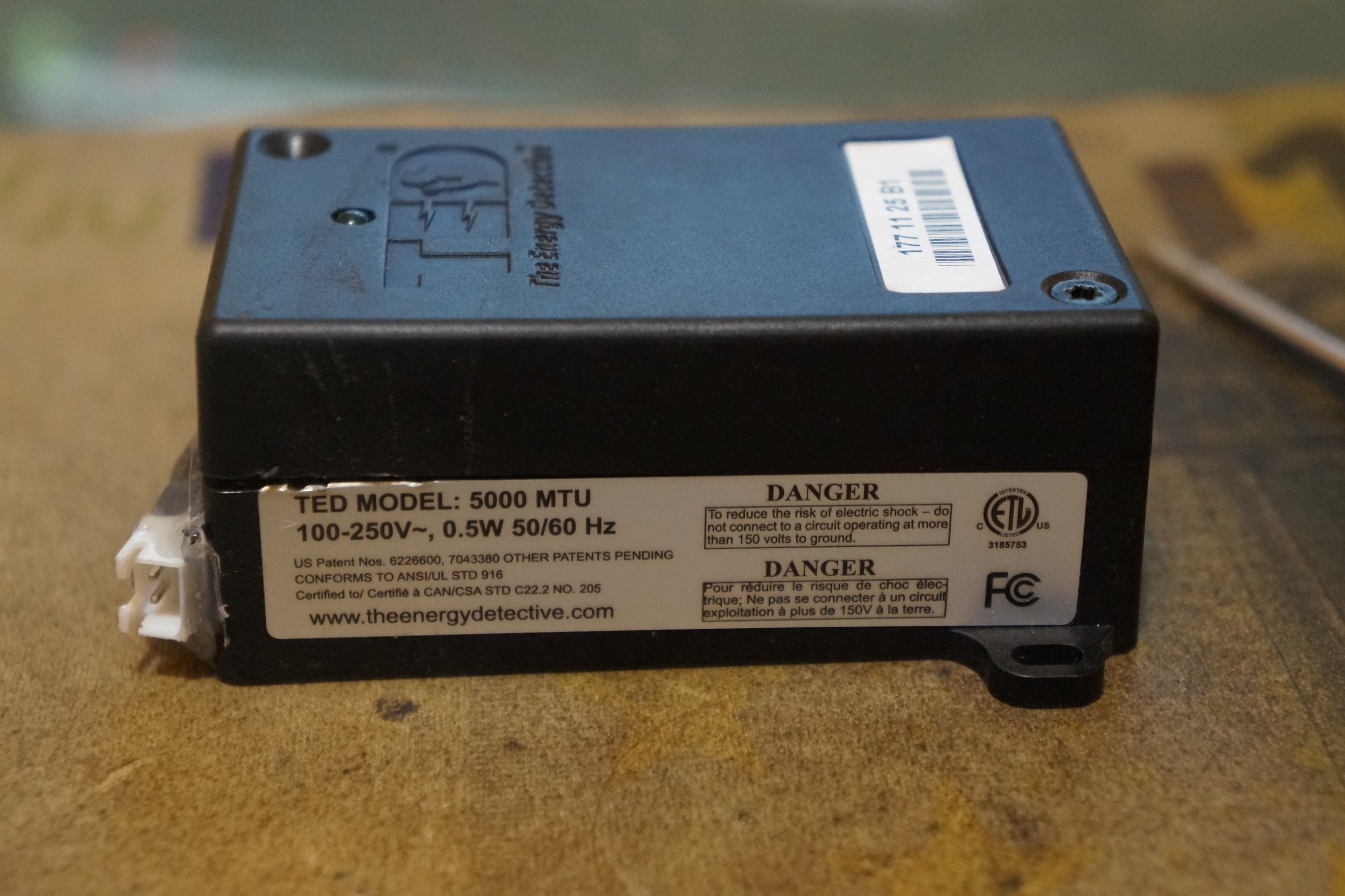
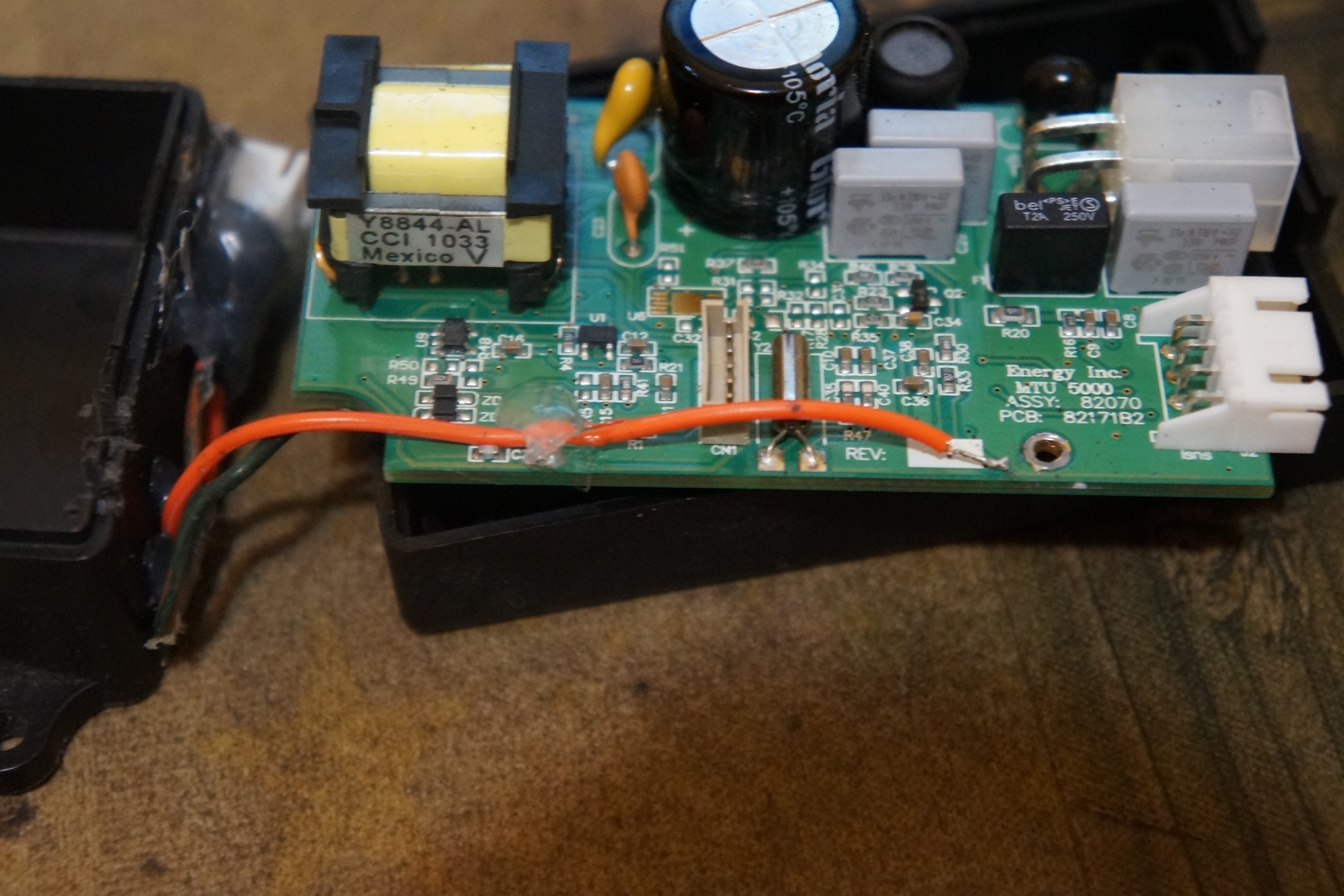
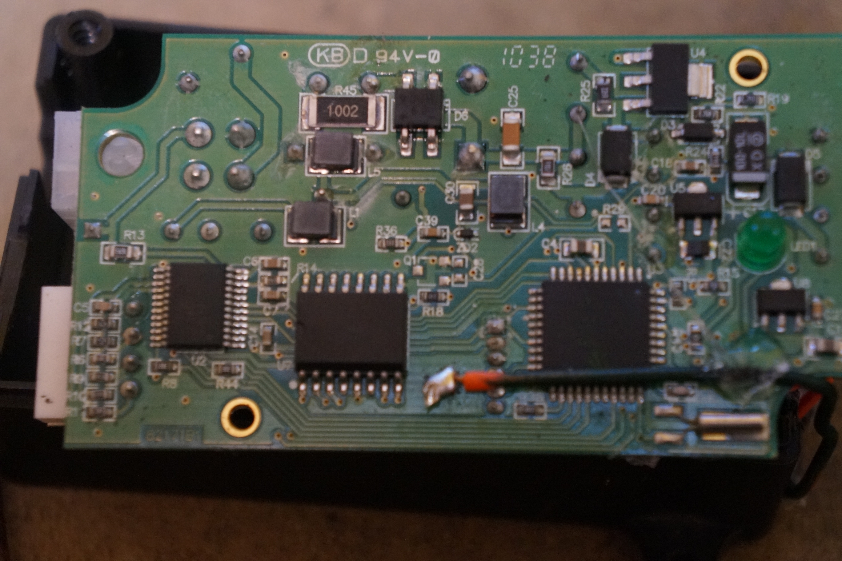
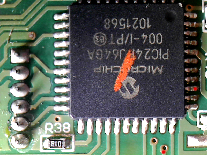
this is a snap shot of the MTU 5000 MTU, I believe the 1000 mtu uses the same chip and the data stream is the same as my software for the RDU works with either the 5000 mtu and the 1000mtu
the red dots signify the trace and the pin that I am capturing data from then MTU micro controller with the esp8266 and the ardiuno . these pins go directly to the power line encoder … TDA5051A modem pin one DATA input
so I think they both use the same modem so you just need to connect to this pin on your older MTU (if using different modem you just need to determine the DATA IN to connect to) and then to RX pin on the ardiuno or esp
to bad your RDU does not work you could of easily tap and esp into it … using the same direction as this guys as he did for xbee and the above software would of worked the same for it…
Cool I appreciate your hard work. I have a slight issue I tried your wifi sketch and the readings are off compared to what the RDU displays. What areas of the sketch does the calculations? I would like it to get it spot on. Again I appreciate all the effort you took into getting this working.
My RDU power line communications doesn’t work I need to connect it directly to the MTU TX>RX RDU to see any data. I’m trying to use a HC12 to transmit from MTU and receive on RDU but it doesn’t work data comes through but RDU doesn’t recognize the data or the timing is tied to the power line modem clock and it doesn’t get the data. I need to resolve that issue before digging into the calibration.
did you slow it down the serial connection to 1200 on the hc12 ( the default is 9600) still do not know why the value is incorrect for you they always displayed the correct kw for me either via MTU or RDU connection
yes I made the default baud to 1200 on both units the data is coming in fine. I have the esp8266 connected to the receiver HC12 and its streaming in data but the power calibrations is still off. I commented out the calculation part if the code to get the raw data and I’m unsure if its getting the correct data. I have a different MTU that also might be the problem. take a look at the serial output below
21:55:41.737 → Publish message: { “devices”: “A”,“payload”: {“Voltage”: 118.76,“Power”: 65316.00}}
21:55:43.495 → This just in … A3 39 F9 DA 0 31 17 98 4 BD
21:55:43.749 →
21:55:43.749 → Publish message: { “devices”: “A”,“payload”: {“Voltage”: 118.80,“Power”: 65317.00}}
21:55:45.475 → This just in … A3 37 47 DC 0 99 22 98 4 FC
21:55:45.742 →
21:55:45.742 → Publish message: { “devices”: “A”,“payload”: {“Voltage”: 118.75,“Power”: 65315.00}}
21:55:47.499 → This just in … A3 35 8 DB 0 1D E3 97 4 FA
21:55:47.767 →
21:55:47.767 → Publish message: { “devices”: “A”,“payload”: {“Voltage”: 119.04,“Power”: 65316.00}}
21:55:49.469 → This just in … A3 33 60 DB 0 83 F0 97 4 31
21:55:49.766 →
21:55:49.766 → Publish message: { “devices”: “A”,“payload”: {“Voltage”: 118.98,“Power”: 65316.00}}
21:55:51.466 → This just in … A3 31 2C DC 0 5 E9 97 4 EB
21:55:51.736 →
glad you got it working I wonder what change in Arduino IDE that the original stopped working. and curiously why did you not have to do the same to the voltage…