STM32 Hardware Development

Well, this might be a bit subjective, but here are my reasons:

  1. I prefer to use a proper web-based documentation and a git code repository with good examples over a tool that I have to install (and that was originally not even running on Linux without tricks).
  2. The different layers CMSIS, LL and “HAL” confuse me. For simple tasks like sending data over a UART, the STM HAL does not really abstract the hardware enough. And if I want to use special features of the microcontroller I can just take the reference manual and set the registers directly. Otherwise I need to read about the features in the reference manual and afterwards find out in some other documents how to actually implement these features using HAL functions.
  3. mbed or other generic frameworks allow to write more portable code, that does not run only on STM MCUs.
  4. mbed syntax as easy to understand as Arduino, or even better, as PWM signals are not named analog (!) outputs.

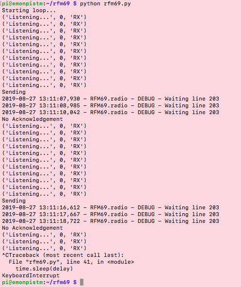
However, mbed also caused some headaches. For example, several times the firmware that worked before suddenly stopped working after an update of the mbed version. But you can prevent PlatformIO from updating mbed and then it’s fine (if you use PlatformIO aswell).

Unfortunately, the definition of custom boards is a pain in mbed. I failed to set up a board with the STM32L452, which is not officially supported by mbed. That’s one of the reasons I’m now also trying out Zephyr. In the long term, I’d love to use Risc-V microcontrollers once they become available for the low-end segment. And mbed will of course never support them. Zephyr is not limited to ARM micros and supports also ESP32 for example.

3 Likes

Having discovered RISC-V only about a month ago, I really like the idea of it being more available at good prices, it could be really great.

I have the ESP12 module working now. Had to cut tracks to swap the tx and rx again :slight_smile:
I need to connect the NRST of the STM32 to the RST of the ESP too.

I think at the last meeting we settled on an esp32 module anyway. Yesterday I found mouser supply them with 16MB of flash, cheap.

1 Like

More notes:
The LEDs I’ve designed to draw about 15mA. I want to lower this to 10mA if the LEDs can be bright enough. 25mA is the max at any pin. 80mA is the max for ALL pins. This is to keep well away from the max ratings.


Chatting with Emrys in the office he was asking into the purpose of an onboard microSD card slot... So the microSD card would give large data storage to an ESP. Then the question was why is that necessary? If the ESP is posting data over wifi, most likely to emoncms.org, then it might not need a local store. In this case, the SD card would act like a backup. Then the thought occurred to use the flash memory of the ESP module as the backup.

Another case would be the SD card of an rPi base station flopping. Again, the flash memory of an ESP module could again store some useful, perhaps daily averaged (365 4-byte datapoints per channel per year? 17,520 bytes for 9 CTs and 3 VTs?).

Then it follows, someone may want to use an SD card on-board for another reason, or for large volumes of high-res data. In which case a 2.54mm header for an SPI/I2C microSD card module would make it straight forward to add that functionality.

So I’m ditching the microSD card adaptor footprint idea for saving on cost and PCB space. Unless someone can convince me otherwise.
Searching ebay I find this. Seems an easy plug in solution for the end-user!

Just got my laptop back up and running after my ssd died.
Next, testing TX/RX and then SPI transactions between the rPi and STM32.

Got SPI pins checked but no transations yet. The next revision will have even more solder jumpers :slight_smile:

I’ve spec’d a 0.47F supercap for Vbat, stopping it discharging using a P-channel MOSFET.

47

1 Like

Hello,

I’ve just found out about this project from Twitter, and it’s very interesting! I’m looking for a board that allows to connect multiple CT and get the data over wifi, and it seems that it’s exactly what you are doing !

@danbates Do you need any help with the code? I’ve some experience with STM32 (mainly F4 serie) and ESP32.

@JF002
Hi!
Sure! The ESP32 I’ve never had a hack at so, yes, help appreciated. I’ll be posting if and when getting quite stuck…
Are you happy to be going down the HAL driver route with the STM32? If yes, then input there’s possible some time too.
We have another here who’s helped a lot so far, @dBC, who’s helped us get set up with HAL and LL drivers.

TVS diodes on BIAS and all ADC inputs.


28

The 5V and 3V3 connections and clamp connector signal lines should need protecting too.

Looks like you guys are making great progress, well done. How’d you get on with DFU? I played with it once on a Nucleo and it seemed to work as advertised. I used a Linux program called dfu-tool.

Hey there, yes DFU isn’t working I think because I need a 1.5kOhm pull-up on the data line. I had to trace the info back through 3 manuals to find this out.
I’ll test when next in the lab, thanks for the reminder as for some reason it slipped off the radar! Now on the list…
dfu-util I found also. Seems like the best cmd line tool for this.

1 Like

Are you happy to be going down the HAL driver route with the STM32? If yes, then input there’s possible some time too.

Well, the last projects based on STM32 I worked on were based on the older library (Standard Peripherals Library Drivers, StdPeriph). I think HAL is the evolution of this library. As far as I know, it’s more generic (the same function for multiple MCU), but with a bigger overload (over writing/reading directly in the registers).
My experience with StdPeriph is that it does the job (configure the peripherals, clocks,…) but most of the time, I had to read the reference documentation of the MCU to understand how I should use it (in which order should I configure which register, which value should I use,…) and then translate the information from the doc to function calls to the StdPeriph.

I did not use the new HAL and CubeMX a lot (I changed job when they were released) but I had the impression that they encapsulated more things, and that I did not know what all this auto-generated code was doing.

But I would be happy to work again on these chips and investigate how to program them nowadays!

Regarding the ESP32, I do a lot of hobby work on them, and I’m quite happy. You can use the Arduino framework for the ease of use and for the available libraries, or the low-level SDK provided by Espressif (called the IDF) if you need more control on the memory and peripherals.

1 Like

Okay, thank you.

Out of interest which pins would you use for SPI and I2C on the esp32?
I see there’re choices. I don’t know if there are pros and cons to them.

For SPI, you should be able to use most of the GPIO for both SPI controller, but they have their own preferred pins, which allow bus frequency above 40MHz (up to 80Mhz, if I recall correctly). It’s all explained here : SPI Master Driver - ESP32 - — ESP-IDF Programming Guide latest documentation

Here are the default pins:

Pin Name HSPI VSPI
GPIO Number
CS0* 15 5
SCLK 14 18
MISO 12 19
MOSI 13 23
QUADWP 2 22
QUADHD 4 21

I used SPI (the HSPI one) on a project with these default pins (15, 14, 12, 13) without any issue.
I would also avoid to use the pins used during the boot the enter into bootloader mode (BOOT0/BOOT1, I think) in order to avoid boot issue.

I’ve every used I²C on ESP32, but I would assume it should work in the same way than SPI.

1 Like

I can’t find any reference to QUADWP or QUADHD online.

But it’s wired up now :slight_smile:

07

Still working of SPI design… I’ll post again in the future on this.

@dBC can you share something on listening to Serial data on the stm32? Tx/Rx transactions between the rPi and stm32 is on the cards to test this coming week.

So far I’ve found:

HAL_UART_Receive(&huart3, &echo, 1, 100);
debug_printf(echo);

…which I think I can use in the main loop. This look right?

Cheers

Yep, provided all you want to do is test the wiring between the two that should work fine provided that’s all you do in your main loop. When the time comes to incorporate it into a bigger project with other things to do you’ll need to come up with something more sophisticated.

1 Like

How can I make sure that the Serial port on an emonpi/emonbase isn’t being used by emonhub or anything else?

I need to use it for testing the stm32 interface using a python script.
@pb66 ?

Should be just:

sudo service emonhub status

and:

sudo service emonhub stop

:slight_smile:

1 Like

Got it, UART1 catching data from rPi, transmitting then on UART2.

11

Seems like these more basic HAL functions are useful for fixed data-lengths.
DMA or Interrupt modes are going to be better for us to use I think, for varying data lengths.

RFM69CW testing:

I’ve got an rPi talking to an RFM69. Basics from here.
https://rpi-rfm69.readthedocs.io/en/latest/hookup.html#wiring
The python wrapper is based around the (much better) LowPowerLab library.

I’m changing our stm32 board to match this guide. Or… do I change it to match the existing emonPi pinout?

Confirming the pinout…
The emonPi is making use of the ATMEGA for sending data thorugh the radio module.
Trys and Glyn I think want to have the rPi doing the comms management, it’s better.

I’ll include solder jumpers to connect the stm32 to the rfm69. The default then will be rPi/ESP connected to the rfm69. We do already have an stm32 functioning with rfm69 documented, so including the code as an option, without ESP or rPi, exists.

Cheers.

P.S. I had to do this outside of our stm32 board, because I had different routing from the rPi library here. Although there’s a way to override pinouts, I tried it and I couldn’t get it working.
Hence changing the routing for the next revision :slight_smile:

Scroll down for board-revision update.

A prototype 3D printed enclosure here. I received lots of advice on injection moulding yesterday from the manager of our local fabLab.

It’s a lasercut piece of acrylic ontop.

SPI testing

I’ve got some outputs with SPI this morning. Following a guide here.

An F103RB Nucleo is sending over SPI as master:

/* Infinite loop */
  /* USER CODE BEGIN WHILE */
  while (1)
  {
    for (;;)
    {
        char message[] = "Hello, World";
        HAL_GPIO_WritePin(GPIOB, GPIO_PIN_6, GPIO_PIN_RESET);
        HAL_SPI_Transmit(&hspi1, (uint8_t *)message, strlen(message), HAL_MAX_DELAY);
        HAL_GPIO_WritePin(GPIOB, GPIO_PIN_6, GPIO_PIN_SET);
        HAL_Delay(10);
        //HAL_GPIO_TogglePin(GPIOA, GPIO_PIN_5);
        //HAL_Delay(1000);
    }
    /* USER CODE END WHILE */

    /* USER CODE BEGIN 3 */
  }
  /* USER CODE END 3 */
}

and an F476 running Analyzer2Go demo.

Wired together:

here’s the Analyzer2Go screen on Windows:

Nice.
So that’s stm32 as master.
I need stm32 as slave.
and run a program on the rPi as master eventually.

Next tutorial: Connecting 2 STM32 boards via SPI – VisualGDB Tutorials


Top Right: Master.
Bottom Right: Slave.
Left: Analyzer2Go.

Getting glitchy comms:


Only single character ‘H’ back and forth works, only some of the time. I’ll be diggin into this another day unless someone has a look at this first?

uploaded to git so far as test2.
. https://github.com/danbates2/STM32/tree/db/Software

For reference: This post and reply has an intro to the idea of using a counter at the stm32 slave, to ensure integrity of the data.

New board revision here:
Checking it over now… could have another prototype on it’s way by end of day.

Had an interesting chat with Glyn about manufacturing / testing processes. Having pogo-pin compatible testing points and a proper testing rig, because, the reality of manufacturing demands we find faulty board quickly!

UART flashing fixed in this version, and a bunch of SPI related changes, and we now have the ESP32 footprint on-board. Going as far as possible with SMT too, instead of through-hole.

Cheers.


(noticing the board outline is very faint, it is there.)

v0.6 stm32-pi.sch (1.4 MB)
v0.6 stm32-pi.brd (524.3 KB)

1 Like

I’ll be keeping major news updates on the other thread and use this thread for any detailed dev.

Cheers

Hi @dBC, happy new year!
Quick few questions here if you’ve got a moment.

When using the timer to trigger the ADCs, does the timer continue to pulse every interval x? and does this effect the functioning of the ADCs continually?

I seem to have a situation where what looks like ADC 1 and 3 are slightly out of sync and I’m trying to get to bottom of it. Possibly it’s because the chip’s been re-flowed a couple of times, it’s had a lot of heat and something could have been put of of whack, hard to say, ordered a new chip just in case.

Connected issue I think: also getting low readings on one of the ADCs, only 80% of what’s expected based on the previous protoboard; 200Vrms instead of 250Vrsm, triple checked all the resistor values, op-amp and the VREF input, which is connected to the 3.3V reference, and I can’t find a fault, another reason to get a new chip… I’ve gone over the code a few times, it’s copy and paste from the working program.
Have you had a similar experience? Here’s the out-of-sync ADC conversions showing up on VREF. I don’t remember seeing this on the previous board.

1 Like