STM32 Development

Hi Trystan, All,

I have found my problem, it was down the project name. I had called it Blink example and Linux does not like spaces in the project name. Calling it Blink and the make command seems to work okay!

Thanks,

Paul.

1 Like

If you quoted the whole name, that normally works. Otherwise, it sees the two parts of the name as two parameters, and loses the plot.

e.g.

$ cd "/home/r/OpenEnergy/Software/RAE/1V_REF/cm/Scope pictures"

Hi All,

Regarding the 1/2 VDD ADC reference, I built up a circuit using two 10k resistor divider from AREF (my AREF is from an LT6656) and decoupled with 10uF. This was buffered by a TLV2333 zero drift opamp. What I found was that the opamp did not like being connected directly to the current clamp circuits as it caused the opamp output to oscillate, and it also did not like the output being shorted out when the current clamp was not plugged in. I have been prototyping on the emonTxShield. I found I had to add a 1k in series with the opamp output, decoupled again by another 10uF capacitor to keep the opamp stable, and then have a separate RC for each ADC, one for the voltage, and one for the current measurement, so that the signal from the voltage input did not couple across to the current input via the common 1/2 rail bias circuit.

You may not have this problem with the opamp you are using in the processor.

Thanks,

Paul.

1 Like

Getting back into STM32 development here, I’ve made progress this weekend getting the reading of meter data using MBUS to work, an important feature for the heatpump monitoring application that we intend to include in the standard hardware. The implementation so far uses the STM32 DMA buffers to request and receive the MBUS data in the background which should make this compatible with other things going on at the same time e.g continuous sampling of CT’s. Here’s the code so far, it’s quite simple, but took a surprising amount of time to get to work as DMA uart communication is a new thing for me https://github.com/openenergymonitor/STM32/tree/master/MBUS/MBUS1

1 Like

Some test results on the v0.5 proto board.
The 9 CT inputs are tested with the same load, a 2kW fan heater (fan is on).
Between the 9 CTs, there’s an error of 1.04% from standard deviation.
The calcs are at the bottom of Sheet1, graphs on Sheet2.

Archive.zip (34.9 KB)

Looking at the channels with most noise, I related the noise to a couple of aspects, the tracks between analog and digital crossing near CTs 1&2. Also, the noise is slightly lower where the BIAS connects at the middle of the CTs and trees out. Next board revision then to have something like a ‘ring’ trace as a BIAS, as well as more careful routing to separate analog and digital traces.

@Paul_Tesla I’ve added an LT6656 to the next order to compare to a couple others, I’ll need to test a few and report back. The MCP1501 reference I tried before had an output very sensitive to capacitance, I need to test it a bit more but I’m fairly sure it’d need a LPF and buffer. Hopefully the LT6656 does better without needing a buffer.
No problem with opamp oscillations on this chip and setup, 10k-10k divider input with no decoupling cap.
I think we have a similar RC arrangement for each adc channel, scope hasn’t shown any obvious crossover.
I do wonder how much energy from the VTs is coming back through the opamp.

1 Like

Season’s greetings.

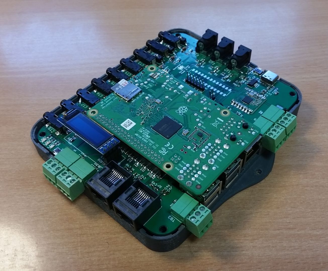
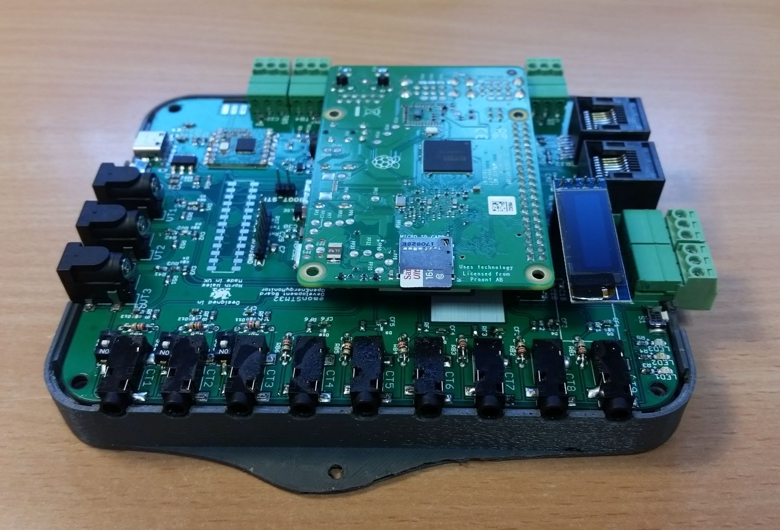
The STM32 project’s coming together. I’m excited to put this one together.

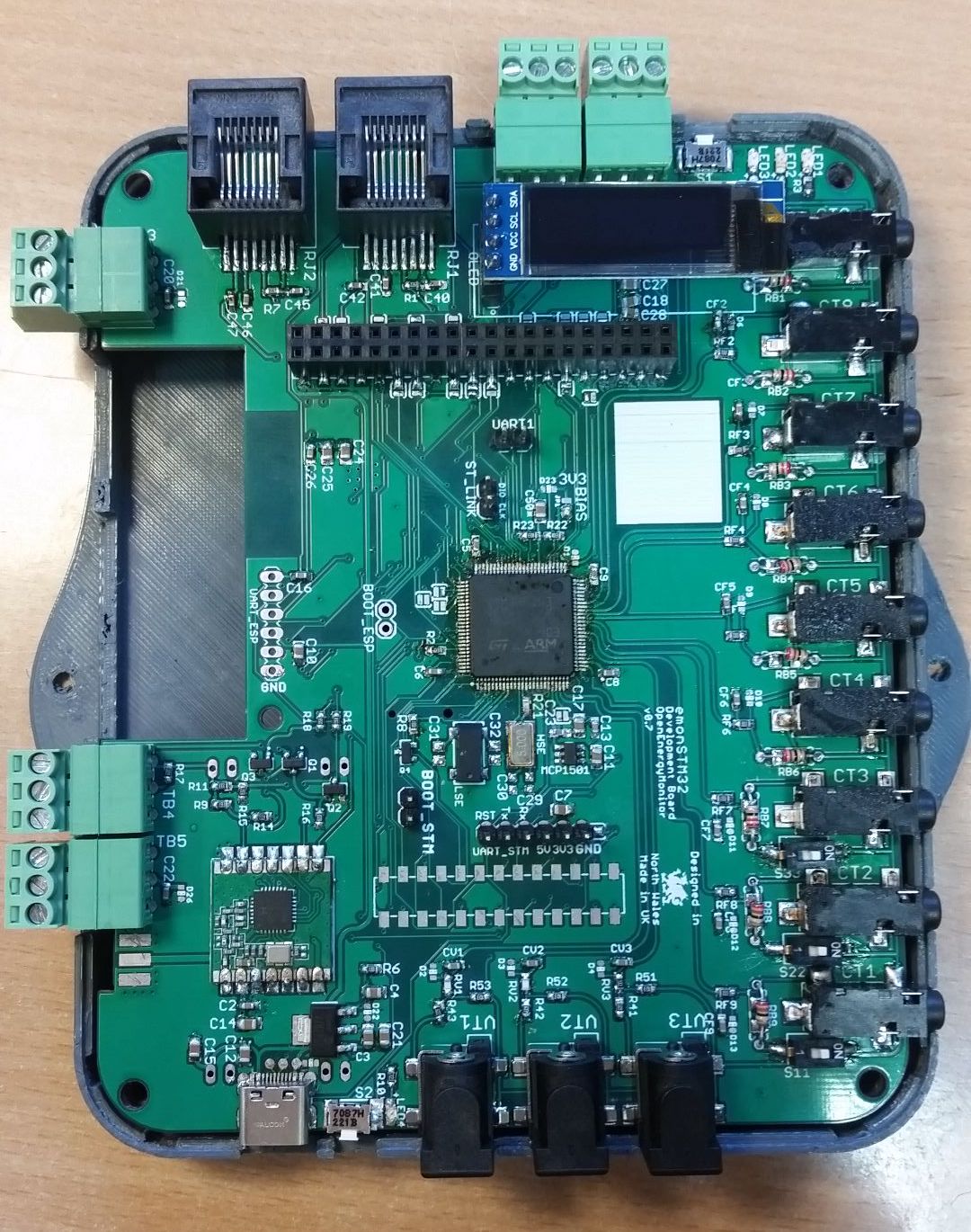
It’s now a 4-layer PCB.

Pluggable terminal blocks are a change worth a mention, very easy to use and manage wiring, for some added I/O.

USB-C now, sample provided by www.toby.co.uk, had to hunt for it from looking at the USB-C conn on the rPi4, it’s the same component and happens to be good value. Device Firmware Upgrade is something to test and try get working in the new year.

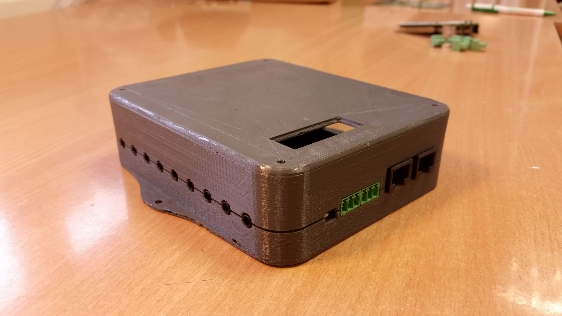
Below’s a prototype enclosure, 3d printed at Bangor Uni’s FabLab at Pontio. Some more changes to make before injection molding.

A footprint for the ESP32 module is on the underside. I haven’t started looking at using it in detail.

stm32 v0.7 eagle_v7.brd (686.6 KB) stm32 v0.7 eagle_v7.sch (1.1 MB)

5 Likes

This is looking fantastic @danbates nice work!

@danbates, Looks great, I’m very interested in the EmonSTM32 as opposed to the EmonTX.
Any idea on your time to market? :slight_smile:

This implementation caters for attaching the external temperature sensor any chance of adding an external humidity sensor as well as an option?

Hi @rabievdm
No exact date yet. The project is moving again since yesterday, the first day back after two weeks away :slight_smile:
A coincidence on the temperature sensor question, this was discussed yesterday, we have both the RJ45 and terminal block options available and we were looking at how well the solutions worked. It’s looking good.
Humidity, I asked this question yesterday (have you bugged our lab ? :grin: ) since we have temperature probes but humidity data is gained through the emonTH at present. It should be possible to connect a dedicated humidity sensor, it’d then be a matter of programming, the pluggable terminal blocks will provide one-wire interfaces, and I’ve routed the rPi’s I2C interface to them also so it’s accessible externally.
When I last looked at this subject a year ago there was a combined temp/humid/pressure sensor which looked good, BMPsomething I think, I can’t remember exactly. Do know of any particular devices?

RPi?

Shouldn’t that be STM32?

Actually, it’s both.
An idea is to have the STM32 detect if a rPi is present, and put some of it’s I/O into the relevant modes.
I haven’t done the tests and checks necessary of this prototype to know if certain aspects of the hardware config, such as this parallel I2C config, is even feasible, should be. CubeMX has been useful in working out some of this early stage design, so far, looks compatible.
We know I2C is a master /slave bus, I believe the stm32 should go into slave mode if the rPi is connected. I don’t envisage it doing anything useful in slave mode, so effectively it’s just settings the two pins as inputs and leaving them be.
At the moment there are a few arbitrarily selected gpio connecting the stm32 and rPi, as well as I2C, UART and SPI.
That’s the easy part!
That make sense?

Dunno if it “makes sense,” as I’m not a coder or low level hardware type by trade,
but at least it explains the RPi part. :wink:

1 Like

:smile:
Oh yeah this is meant to be an STM32 development thread!
hehe. Well noticed.
When it comes to things like I2C I’ve been leaning in the direction of offloading work onto the rPi, making sure the STM32 can catch all those lovely samples we have planned for it.
I know the rPi can handle it, whereas the STM32… hmm, probably. We’ll have all these peripherals dangling off it at some time to see if the CPU gets 100%ed. See how it goes.

The 3-wire pluggable terminal block. 3.3V, Data, GND.
Between the two blocks, I2C is available.

2 Likes

Just had a look on CPC and the plugs seem quite expensive really. With 5 on the board it must add to the cost unless there is a really cheap supplier somewhere. A good idea to have some sort of pluggable solution though.

Do the RJ45s do the same job? If so then the splitter block could be a solution to a pluggable interface.

Just a thought :grin:.

They’re not at all expensive. Have a look at RS.
. https://uk.rs-online.com/web/p/pcb-terminal-blocks/1444326/
. https://uk.rs-online.com/web/p/pcb-terminal-blocks/8971001/

OK great. I couldn’t find them and what I did find were 10x that price.

RJ45s are a real pain to crimp - these look like a much better solution. No special tools, just a screwdriver.

Simon

2 Likes

I agree, these are really nice, I’ve been wondering if it might make sense to replace the CT jacks with these connectors to enable shortening and extending of CT cables for a neater install…If we can get them for the right price would it be a better solution?

Oh yes, I was suggesting the expansion board so a pre made network cable, then the screw terminals. Just a thought.