Yes, exactly that. Everything is in A/D units all the way through, and then at the last minute you can convert them to real world units based on resistor dividers, shunts, calibration constants etc. I tend to favour that approach because that’s how it all works in the energy IC world. Who cares about actual Volts, Amps and Watts, you can do that conversion on the final dial display. And if your meter is performing well, you’ll only need to calibrate Volts and Amps, and you’ll get Power for free.
There are some disadvantages to that approach, like is 75.xx a big number or not?.. if it were already in Amps you’d know but your brain eventually adjusts. Anyway, that’s just a personal preference, it ultimately shouldn’t make any difference to the answer where you convert them to real world units, so use whichever you prefer. Your Irms of 75.50 means 75.50/4096 * 3.3V = 60.8mV, so quite small, and smaller than the noise on your unterminated inputs. To work back from that to Amps going into you kettle, you’d need to do the CT/shunt maths. If you’re up for doing that, I’d be kinda’ interested to know what answer you get, because I think you’re the first to wrap the CT around a real load.
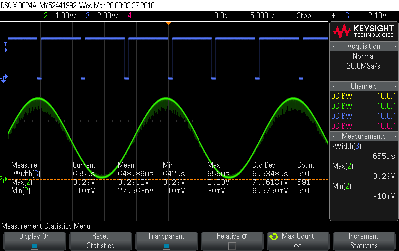
To give you a rough idea of scale, I’m feeding all my inputs (V + 4*I) this sine wave:
and you can see it’s close to full-scale deflection (Vpeak of 3.29V and Vmin of 27mV). That gives these readings:
CPU temp: 38C, Vdda: 3304mV
0: Vrms: 1394.68, Irms: 1394.44, Papp: 1944800.12, Preal: 1944781.12, PF: 1.000
1: Vrms: 1394.68, Irms: 1394.28, Papp: 1944575.00, Preal: 1944561.38, PF: 1.000
2: Vrms: 1394.68, Irms: 1394.11, Papp: 1944338.12, Preal: 1944327.38, PF: 1.000
3: Vrms: 1394.69, Irms: 1394.26, Papp: 1944573.38, Preal: 1944549.25, PF: 1.000
BTW, if you look in power.c you’ll see I indicate clipping by changing the “:” to a “>” just after the channel number, like this:
CPU temp: 38C, Vdda: 3304mV
0> Vrms: 1394.38, Irms: 1394.16, Papp: 1943993.12, Preal: 1943957.25, PF: 1.000
1> Vrms: 1394.38, Irms: 1394.02, Papp: 1943788.00, Preal: 1943759.12, PF: 1.000
2> Vrms: 1394.38, Irms: 1393.90, Papp: 1943633.00, Preal: 1943600.50, PF: 1.000
3> Vrms: 1394.40, Irms: 1394.05, Papp: 1943860.00, Preal: 1943847.12, PF: 1.000
Well, possible clipping. It does that if it sees just a single reading of 4095 during that 10 second integration. If it’s just kissing 3.3V than 4095 would be a valid reading so “possible clipping” is probably more accurate than “clipping”. The chances are if you’re hitting 4095 then it’s probably wanting to tell you 4096 on some readings, but can’t.
Yes, that would be my guess. You can see in my numbers above, where I’m bypassing any sensors and feeding a signal straight into the inputs, I get a PF of 1.000. You could try using the ADC-lag feature to calibrate that away. The first thing you want to do is move the two sine waves well away from each other, so that the numbers are bigger. I use 60° when calibrating my energy IC, because I need meaningful Real and Reactive numbers (I use arc-tan rather than arc-cos) to calculate the phase error. But as Robert suggested above, you could use 90° in this case. Then the Preal number being spat out would actually be Preactive and since your dealing with a resistive load, it should be 0.
You do that by editing the call to start_ADC():
start_ADCs(5000); // start ADC with x usec lag
A cycle is 20,000 usecs, so 5000 usecs is 1/4 of a cycle, or 90°. Here’s what I get when I do that with my full-scale deflection sinewave from above:
CPU temp: 39C, Vdda: 3302mV
0: Vrms: 1393.60, Irms: 1393.86, Papp: 1942492.25, Preal: -2365.41, PF: -0.001
1: Vrms: 1393.60, Irms: 1393.73, Papp: 1942301.50, Preal: -2353.97, PF: -0.001
2: Vrms: 1393.60, Irms: 1393.77, Papp: 1942366.88, Preal: -2371.13, PF: -0.001
3: Vrms: 1393.59, Irms: 1393.72, Papp: 1942268.38, Preal: -2350.05, PF: -0.001
Not quite 0, but close compared to Papp (remember we’re dealing with full-scale deflections here). So to work out my phase error (which ideally would be 0 given I’ve got no magnetics involved) I do an arccos (2365/1942492) which is 89.93°. You can ignore signs in all this. I’m aiming for 90° because I’ve turned my purely resistive load into a purely reactive load. So somewhere I’ve got a 0.07° phase error. My guess at the source of that would be that the signal generator’s idea of 50Hz is slightly different from the F303’s idea of 50Hz.
So if you do all that, you’ll get a pretty good estimate of what your net phase error is (i.e. VT + CT combined). Let’s say it comes out at 2°, you can then turn that back into a usec value: 2/360 * 20000 = 111 usecs (or possibly -111 usecs since we’ve ignored sign in all this) and use that in your call to start_DACs() and you should get much closer to a PF of 1. If it makes it worse, you need to change the sign… i.e. 111 Vs -111.
If you do manage to nail it, you’ll then get a feel for how sensitive it all is to a whole bunch of things including:
. line frequency changes
. V changes
. I changes.
These were all the things I planned playing with when my shield arrives, but feel free to start without me if you’re up for it.


