[Note -This started out as a PM thread following on from the STM32 Development - #140 by ian thread, the PM has now been made public so others may join in]
Hi Paul
I have done some preliminary work on a shield using the morpho connectors on the nucleo 64.
I am no circuit designer, I am a CNC machine tool retrofitter by trade. Initially I have replicated the EmonTX shield using the morpho connectors instead of the Arduino connectors. I have made no effort to change any values to reflect 3.3V.
I also wanted to see how easy it would be to fit more CT sockets. As you expressed interest in PCBs I attach the preliminary files for your observations. It looks as if 8 CT & 3 AC sockets could be fitted on the board pretty much as shown.
What I had in mind is really quite different. Perhaps we should start a public discussion?
As I’ve said in the STM32 Dev thread, there is no intention of using the nucleo boards beyond development and I’m looking for something more flexible that I can attach any CT to any ADC channel. There fore the morpho connectors are somewhat wasted when jump wires can be moved around.
We are also not planning on using the voltage dividers for the midrail, instead we want an op amp derived midrail. Although I might be tempted to still include the footprint and holes for the voltage dividers in case the opamp thing doesn’t pan out or even to facilitate a side by side comparison.
The shield is really quite dated now and it doesn’t have any protection for the ADC inputs so we would need to include clamping diodes and 1k protection resisters too on each input.
Also we had determined that the AC voltage divider needs to be a much lower impedance so we can sample the VT much much faster allowing us to have more genuine V samples rather than calculating/interpolating V values from a more sparsely sampled voltage.
To have ample CT sockets is far more important than the size or shape, 8 CT’s just isn’t enough, we are currently debating if 15 or 18 or whether we should provide more for room for expansion over that.
On the production units we do not intend having all the ADC channels on every device, but perhaps a basic 6ish channel device and then some slave IO board that stack on top and use the same processor.
It’s still very early days, hence wanting a flexible proto board type thing rather than a fixed design.
[edit - there is also an error built into the shield that we wouldn’t want to carry forward. The 3.5mm sockets ground the midrail when there is no CT plugged in, the intended behavior should be to short the adc input to the midrail, ie “zero” the CT signal. This is obviously mandatory to remedy if a common opamp midrail is to be used.
Starting a public discussion is certainly a good idea.
Maybe we see how many ideas can be accommodated in one board.
My particular interest is proper monitoring of 3 phases (Grid & PV). We want to evaluate the possible use of a powerwall in a commercial environment, but first we need the data.
With regard to the error in the shield on the 3.5mm socket, for the moment I can’t see how to make it work with the shop supplied CTs. Could the unconnected ring be used to do the switching?
It can be done using just the sleeve and tip, if the midrail is the sleeve and the adc input is the tip, then make the sw contact for the tip midrail too, then the adc input is held to the midrail until the CT is plugged in.
Yeah, we are just trying to get all the idea’s out in the open 1st and then we can start fathoming out what’s in and what’s not, the favorite approach right now is for a stackable/modular design so that the emonTx v3 can be replaced with a basic 4 to 6 CT master board (or master and one slave) and then additional slaves can be plugged in for additional CT’s and more pulse counters etc.
But that is different to what I thought we were talking about here.
We are way off a final product, we need a proto board to help us test the various possible configurations before we finalize any designs, that’s why I want a single proto board with 20’ish CT sockets and plenty of headers so that the CT sockets can be plumbed into any adc channel on the nucleo for testing, hence the morpho connectors would not be useful as the connections would be fixed.
But this “proto” board with loads of link wires to a nucleo is not really suitable for a finished product, I guess you could use it for a few months to evaluate the viability of a powerwall, but I’m not looking for another shield to fit a nucleo, for as long as I’m using a nucleo I want to be able to move the ADC’s around freely and once I no longer need to move the ADC’s around, I guess we will be near to going to production of a STM32 based monitor, so the nucleo’s will no longer be used.
Would you mind if we made this discussion public? or at least invite @RobertWall (and maybe a few others)? As I’m having the same discussion in multiple places and none are public for others to jump in.
How about using narrower 3.5mm jack plug sockets so we can fit more sockets in the same width? I wish I had done this on the emonTx / emonPi e.g the SMT jack plug sockets used on the IoTaWatt or if you want to prototype with thru-hole something like these:
This is the SMT socket used on the IoTaWatt, its a 3.5mm 3-pole with an integrated swtich. The swich is useful for connecting the output to GND when no plug is inserted. This gives as a sure way of knowing if a socket is inserted or not:
Apparently that may no longer be the case with an opamp used for the midrail. @Robert.Wall and I have just recently discussed this and the only sure fire way to detect if a CT input is connected or not is to use a “stereo” version of the socket so the ring’s switch can be used.
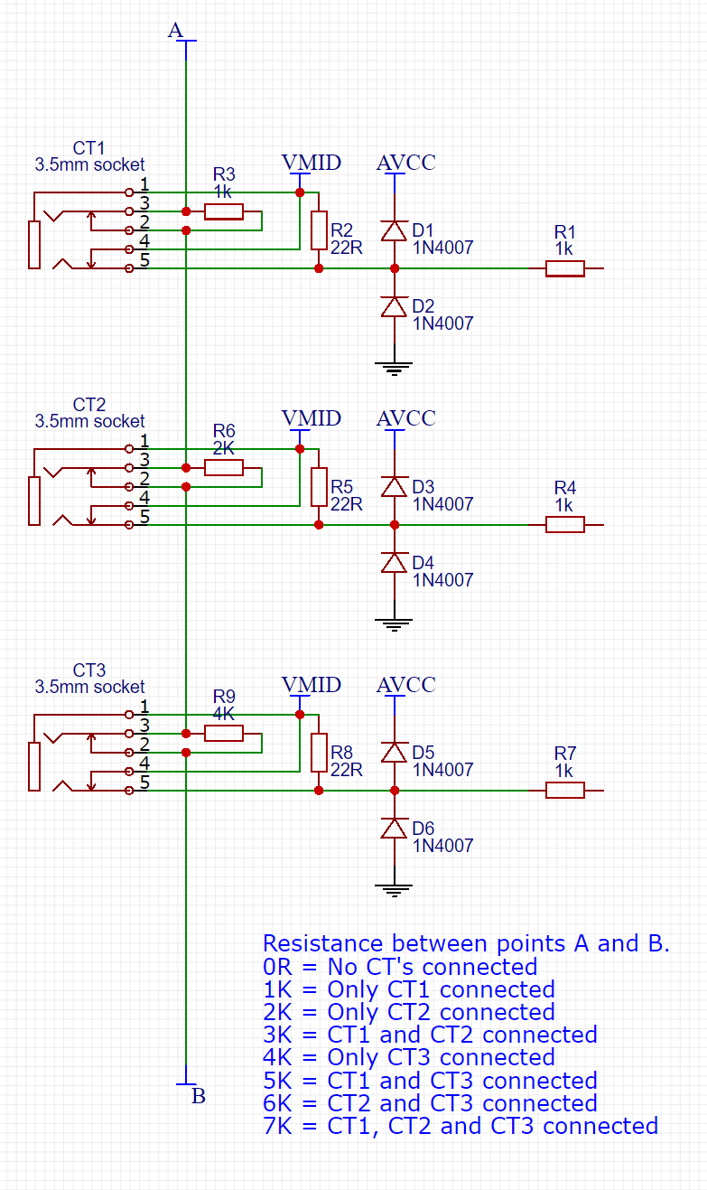
If there are enough DIO’s available you could sense each one individually. but if we have a (couple of) ADC channel(s) spare a chain of resisters can be used to identify which sockets are populated. Like so
This gives us an active fault recognition too, so if a CT gets unplugged we can omit that value rather than reporting it as zero if the way the payload is passed out supports that (eg serially to emonhub).