We’ve got some headroom in the ADC clock speed. It can run 2x or 4x faster than we’re currently running it in the txshield demo. So for example, if we were to go from a 2-slot sequence to a uniquely populated 16-slot sequence and change nothing else, the sampling rate would be 1/8th what it currently is (14.66kHz / 8 = 1.8kHz). But we could run the ADC 4x faster than I currently am (72MHz instead of 18MHz), in which case it would be just 1/2 what it currently is (14.66kHz / 2 = 7,33kHz).
The other place we’ve got potentially huge headroom is in S&H charge time. Currently that is set to the maximum: 601.5 cycles. The entire conversion takes 614 cycles, so it’s currently pretty much all charge time. How low we can take that depends on how low we can get the source impedance of the signal, but currently at least, it’s set as conservatively as it can go.
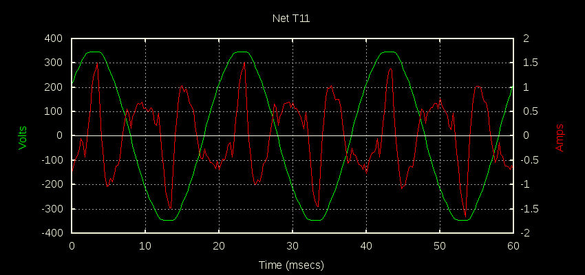
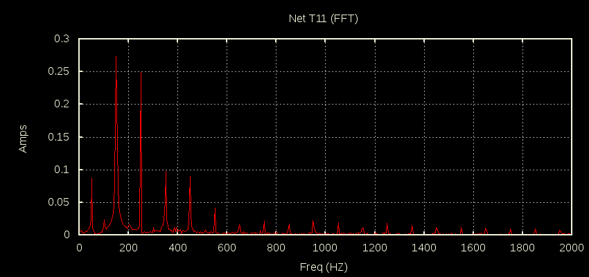
There are two that spring to mind. The first is a CT wrapped around the main feed from the street when there is close to perfect balance between PV output and consumption. In that case the inverter is providing pretty much all the fundamental stuff, and the grid is left to supply all the harmonics. That seems to be one case where you can quite legally violate all the rules about how much energy should be in the harmonics Vs the fundamental. That looks like this:
That’s not a logarithmic scale on the FFT, just straight Irms at each harmonic. Also note the sample data is only 4k samples/sec so we can’t see what’s above 2kHz.
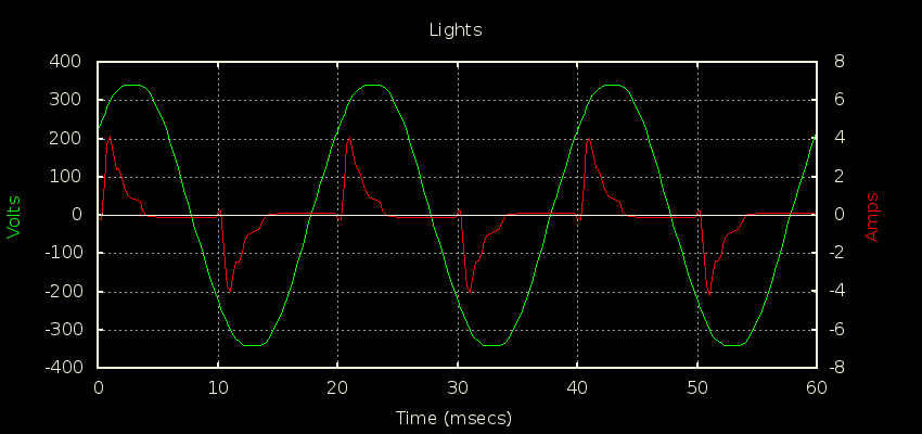
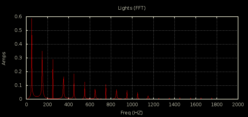
The second one is the lighting circuit when there’s a bunch of CFLs on. It looks like this:
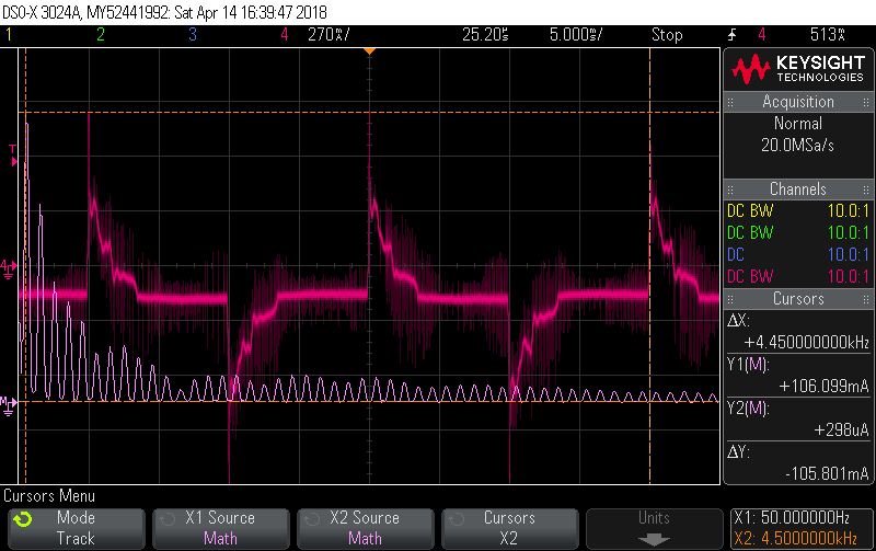
Using the scope’s current probe and just one example of the CFL here it is out to 5kHz:
For some sense of scale, the two cursors are at 50Hz (106mA) and 4.5kHz (298uA). You can ignore the Red trace, it’s the signal in the time domain to verify I’m looking at a typical enough specimen (looks close enough to what the energy monitor reports for the lighting circuit when there’s about 200W worth of these things on). The cursors are tracking the FFT (Violet).
