Smart fridge (demand side management/cost reduction)

I am trying to bodge together a demonstration “smart fridge”. I think the basic idea is sound, but I am technically fairly incompetent, and am struggling with the details.

At the moment, I have a digital thermometer inside the fridge, with a wire out to a Raspberry pi (via the drain hole in the back of the fridge). The pi controls the power to the fridge via a smart plug. The pi switches the power on when the temperature rises above an upper threshold (6.5 degC), and it stays on until the temperature falls back below a lower threshold (4.5 degC). So far so dumb.

What I would like to do now is to use the fridge to help balance supply and demand on the national grid! When supply exceeds demand, the frequency rises above 50 Hz. So I want to bias the fridge so that it is more likely to run when f>50Hz, and less likely to run when f<50Hz and demand is outstripping supply. I am hoping to show that the smart fridge can run mostly when supply exceeds demand.

The bit I am stuck on is getting hold of the frequency. I cannot find an API which broadcasts grid frequency in real time. I have an electricity meter monitoring my heat pump on OpenEnergyMonitor. I can graph the frequency on the dashboard. I am guessing the data is stored in the binary files in /var/opt/emoncms. Is there a short cut to getting hold of the current frequency value? Trying to decode the binary PHPFina files looks a bit intimidating to me.

What does that graph look like, and what is the sample rate of your frequency measurement?

I can’t speak for the UK grid, but I measure / log the frequency here in Aus every 10 seconds and it’s pretty scratchy bouncing either side of 50 very frequently. Here it is at various zoom levels:


Left to its own devices, when my fridge runs it typically runs for about 20 mins. I suspect efficiency relies on you not cycling the compressor too frequently, but you might struggle to find a 20 minute interval when the frequency is reliably above 50 Hz.

As a side note, they do something similar here with air-conditioners but the signalling is message based from the provider rather than inferred from the line frequency like you’re trying to do. Here’s an example:

They promise to only use mode 1 in an emergency, the other modes are said to be unnoticeable by the consumer.

You can see the frequency change as consumers put load on and take load off (relatively slow changes), and the grid controller responds by bringing additional capacity on-line or taking it off (relatively fast changes). As I understand it, the aim is to keep it within 0.2 Hz (the legal requirement is 1%) and with the same number of cycles per day, so that clocks that count cycles can lose or gain over the course of a day, but don’t exhibit a long-term drift.

1 Like

I wonder if it might be better to rely on an internet service (API) that provides the relative grid “carbon intensity” during the day at half-hourly intervals, or something, rather than trying to detect the local frequency.

Also, it’s probably a good idea to wait for the fridge to finish its cycle before switching it off, to save wear on the compressor. I manage my heat pump in a similar way, letting it decide how long to run for, but I control how long it stays off.

Which reminds me of this story.

Our links to the European Grid are all d.c. :smiley:

Hi,
there are graphs of grid frequency here for the last 10 minutes (Live Frequency. I think he uses a raspberry pi :grinning: to measure the frequency averaged over 0.5 seconds every second.

I assume the spike is some kind of measurement error.

My motivation is that at the moment we are paying fossil fuel power stations and Drax to vary supply to match demand. So my understanding is that sometimes we pay them to switch off (!) when supply exceeds demand. According to Octopus, this adds about 1p/kWh to the price of electricity (Agile pricing explained | Octopus Energy).

image

I think we use 275*10^9 kWh/year in the UK, which would make the cost of frequency balancing about £2750 million! I find it quite upsetting that the fossil fuel companies are trousering all that. I have also read that these costs are going up, partly because of the rise in intermittent renewables, and the corresponding reduction in the number of large generators, which is reducing the “inertia” in the system. It seems obvious to me that we ought to at least try to adjust demand to meet scheduled output. I don’t really care exactly when my fridge runs, I just want it to stay within a certain temperature range. I am not looking to force the fridge to slavishly follow every wobble in frequency, but just to bias it so that it’s more likely to run when the current frequency > long term average frequency. I just want to do an experiment to see if I can boost % electricity consumed when frequency > 50 Hz from 50% up to say 80%. I guess it is likely to shorten the average compressor run from 20 minutes down to say 15 minutes or so, but that would all be part of the experiment.

There are an awful lot of fridges in the UK, which are active 24/7, so I think this approach could be a valuable tool to help reach net zero at an affordable cost. You could also try something similar with heat pumps, raising the room thermostat target temperature (or maybe the flow temperature) say 0.5 degC when supply exceeds demand, and vice versa. It would need to be built into the control system, but maybe the electricity companies would subsidise the upfront cost of heat pumps with this technology. I don’t think very much research has gone into demand response by the grid. They seem to be getting interested, but it’s early days. But I think us OpenEnergy folks could make a real difference with this sort of thing.

PS I was also going to see how much a smart fridge could save in monetary terms if you are on a time-of-use tariff such as Agile. ie if the price in the next 1/2 hour window is higher than the cost in the current window, then bias the compressor to run now. It would also help shed demand from the 4-7pm peak period a bit - especially if you super cool the freezer in the run up to 4pm.

If you’re envisioning widespread deployment, having all the fridges in the country sync’d to the same algorithm might actually make things worse. It might end up like the case where everyone was turning their kettle on during the closing credits of Coronation Street.

It’s pretty common here in Aus and in Germany I believe. Others determine when my pool pump runs and when my EV charges. I don’t have aircon but as mentioned above, if I did, they could wind that back a bit too as needed. But they can control it, and stagger it a bit from area to area.

Careful!

I did this using a smart plug with tasmota flashed onto it and…

…flooded the kitchen somewhat.

Water from the air in the room condenses on the cooling element at the back of the fridge. It then drips down the back wall, out of a drain, and into a bucket on the top of the compressor where it slowly evaporates.

It turns out this process is quite finely tuned to the expected humidity / runtime of the fridge. Run for too long in one go and in my case you’ll ice up the back of the fridge, the water then drains into the fridge, and out of the front of the door…

Demand shifting wise works fine; temperature wise works fine; but control of humidity / condensate / frost is also an art form!

Siemens A+++ rated jobbie from 2013 fwiw.

Freezers are probably safer.

I get the UK mains frequency by local measurement on an Arduino using (howls of fmea from the pro electricians?) a potential divider hidden inside a spare British mains plug. The 22 Meg resistor to Live! Must be safe for mains Voltages and provides a tiny ac current to a low resistor of the potential divider which is in the 20k to 200k range to mains Earth!. The potential divider goes into the base of an npn connected to mains Earth! and to GND and pin D3 (pullup; input) of an arduino, which does interrupt timer logic with 4 microseconds resolution.

In place of an API, you could buy an Arduino and do like mine. The most expensive component in my mains F probe is the new BS1363A plug, unless you scavenged a scrap one. My npn were an unknown ten pence three legs type from ebay with beta above 200.

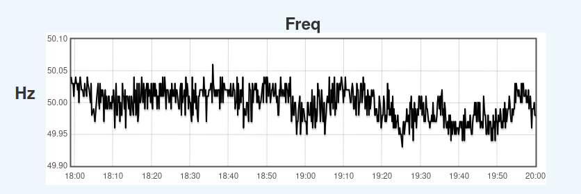
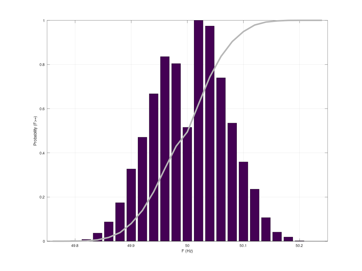
In every mains cycle rising-to-rising of around 20 ms, the function micros() in arduino returns long integers which can be subtracted, giving a long integer of typically 19920 to 20120. Divide the (board dependent) clock calibration number such as 1000800 microticks per second by that, and it gives you The UK mains frequency in the latest 20ms cycle. For most applications you’ll want better accuracy at the expense of latency; for example I maintain an exponentially weighted rolling average with half second lag similar to F25 = 0.96F25 + 0.04F1; from latest cycle estimate F1 of frequency, which should always be inside 49.7 to 50.3 Hz; anything outside of that is a measurement fault.

As a bonus extra, with laborious calibration effort, the duration of the high until low from this single transister probe to interrupt-fine-timer gives some indication; good to about 2%, of the mains rms Voltage, so for example it can spot it straight away when my street is at 232 Volts instead of the more usual 242 Volts; perhaps indication of more local demand than could be visible from the national 50Hz alone. That seems to happen around most evening peaks; perhaps from many cookers being used in my street, so perhaps you could get most of this indication from only timer logic “while time is 5pm to 8pm”.

Rather than using such in hard logic, I’d prefer to “bump the thermostat”, for example tweaking the fridge sensor ON and OFF temperatures from your [4.5 6.5] to ( [5.0 6.0] - (F-50.0)*0.5/0.2 ) with of course numerical conditions checking sensible limits of how much thermostat-tweaking is allowed and whether to accept F as a valid Frequency near 50Hz or to ignore a measurement fault and revert to sensible defaults.

By the way, I also noticed a very ugly turn-on spike from the motor of my unmodified Zenith fridge, and not every time. If one is going to improve things anyway, then to synch your relay switching to the time of the next rising zero crossing of mains V after you decided to activate the fridge might improve that.

Whilst I would prefer an API to read a trusted local status and forecast from a “smart street” valid for everything below my local street transformer, my local DNO were dead against my instrumenting their street transformer, so it would need a private network such as a university electrical engineering building to demonstrate that such can be useful. In the meantime, we only have a national demand indication F to decide from.

Agile is limited to price per half hour block, and since your fridge should normally run for about one ten-to-twenty minutes run in every half-hour block, Agile is incompatible with a sensible fridge temperature. It is missing the extra information of which minutes within the half-hour are least “expensive” to supply your fridge.

The 22 Meg - I wouldn’t trust a single component, no matter what its voltage rating. I’d be happy enough with 4 × 5.6 MΩ in series, then if one fails you’ve still got 3 left to save you from immediate disaster. I hope your transistor is good enough to blow the fuse in the plug, or trip your R.C.D.

@wizzo227 , I don’t think you live up to your name when it comes to safety matters.

As expected, the qualified ones do spot the hazards. I looked at the size of 5.6MΩ which could be fitted inside the available space of a mains plug given my dodgy hand-soldering, and decided that I preferred one extra large ceramic 22MΩ with axial leads. Whilst a custom housing box might in principle allow more room for more safety, by definition it is not safety-accredited if I make it, so I bought a BS1363A.

If my cm long 22MΩ arced, that should break the base to earth of the transistor ???. The only wires leaving the plug are Mains earth to arduino GND and transitor top (C) to arduino 5V high impedance signal in. Since I chose a ceramic R, and was careful not to get finger grease on the outside of it, I don’t expect it to fail short circuit or turn into a blob of carbon or anything like that.

How would you improve on this ?

What if you have a emitter-base-collector short in the die, and then the emitter lead-out wire inside the transistor vaporises? Mains appears on the Arduino input? It could all get quite exciting.

What you really want to do, if that resistor does fail to a low value, is have something to clamp the voltage to earth to (say) 1.5 V for long enough to blow the fuse - and bear in mind the worst case will be if the current is close to but above the fuse rating, when it might take tens of minutes to blow and become safe.

I still think more than one resistor is the simplest and safest course. RS do high voltage (1600 V d.c.) 5.1 MΩ axial lead resistors that are 6.5 mm long × 2.4 mm diameter, but prohibitively expensive as they are only available in a box of 5000! The standard axial lead metal film 5.6 MΩ is rated to 200 V (400 V peak) and 3.3 mm × 2 mm. I think you could get 4 of those in. Have you checked the voltage rating of the component you’ve used?

This doesn’t impress me as you’ve published the suggestion with the clear intention that somebody, somewhere, who stands to know less about safety than you, will be able to copy the arrangement and be unaware of the dangers.

Thanks for the heads up! Our fridge freezer is a Bosch that I bought back in the1990s. It was a B rating then, but that’s probably equivalent to a Z— these days. I think I’ll end up reducing the run time slightly, so hopefully I won’t run into exactly the same issue. But the freezer leaks water when it does it’s defrost cycle anyway, so that might allow me to deflect the wife’s wrath if the worst happens.

I am currently averaging the mains frequency reported by a couple of SDM120 electricity meters that are connected to our OpenEnergy heat pump monitor. They only resolve frequency to 0.05Hz, but I think that’s good enough for me in the short term.

But those meters are quite expensive, and in the longer term, I would like to be able to measure frequency with more precision. But I would want to avoid any high voltage circuits. Would it be hopelessly inaccurate to just use a normal AC mains transformer to step the voltage down to a handful of volts, and then feed that low voltage AC into a frequency measurement circuit? Given that mains frequency is almost always in the range 49.8 to 50.2 Hz, I think being +/- 0.02 Hz of the true frequency would be good enough.

Why should it be? What you’ll get out of the transformer won’t be a totally exact miniature replica of the mains input, but frequency is one thing that can’t change from input to output. And if you use something like our a.c. adapter, it’s totally safe.

I’d suggest going for a phase locked loop, depending on the time constant of the feedback, this will inherently add a bit of smoothing to the measurements, and it’ll easily keep track of the UK grid. There’s even Arduino/emonTx software here - by Martin Roberts (MartinR) in 2012.

https://openenergymonitor.github.io/forum-archive/node/1535.html

And there is a demo/test sketch that does just frequency. As it relies on the ATMega’s clock, it could well need calibrating if the clock source isn’t itself accurate in frequency.
https://openenergymonitor.github.io/forum-archive/node/1377.html

There’s also Nuno Chaveiro’s library (the final post on that first archived page ).

Output of a stepdown AC/AC transformer is a safer place to look at UK mains frequency. You could even use exactly the one transistor probe circuit which I do, with a less officious potential divider down from a safe Voltage such as 12 or 5 Volts rms to activate a transistor on the digital input pins of one of several possible microcontrollers.

Software using interrupts is necessary to get the timing precision which you’ve requested in a single 20ms cycle. Precision on a 16MHz 328 is two parts in 5000 from the duration of a single 20ms mains cycle; call it 0.02Hz. For most decisions I’d normally continue for a few more mains cycles for confirmation.

By comparison to the phase locked loop suggestion, a microcontroller solution depends on the piezo crystal oscillator as its reference standard. On an arduino nano 328 and those seem to drift by up to a minute per week, so there is room for improvement. Those things have a second interrupt enabled pin D2, so it is possible to give it a very regular reference standard to look at as well as the mains.

The plainest sorts of transformers for 1990’s household electronics have a 50Hz laminated iron cored transformer, and are recognisable from being heavy. Some of those built as AC to DC supplies also have a bridge rectifier which can be removed.

Let me know if you want more info on a one transistor 50Hz interval circuit.