Shelly EM energy monitor

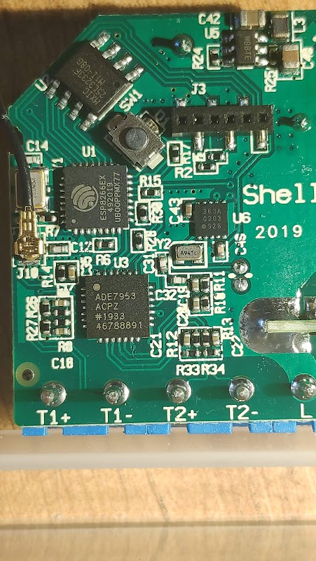
Hi i’ve managed to reverse engineer the shelly EM energy monitor, it includes a ESP8266 with 4MB flash and easy access to firmware uploading.

The energy sensing is done by a dedicated I2C ADE7953 chip that and can measure 1 voltage source and 2 current channels with power flow direction.

There’s also a I2C RTC clock, a relay, a LED and a Button. The package is incredible small.

The original shelly firmware is great, lots of flexibility with REST API and MQTT, and cloud stuff, but it was missing native emoncms support, and that is simply not acceptable… right?

I’ve created a simple sketch and uploaded to my github repo with all the hardware covered and working.

I also have the shelly 3EM which will go next on the bench. This one is more expensive but is very flexible as it can measure up to 3 different voltage sources and 4 current sources. The case is also very small and can be easily mounted on DIN-rail.

1 Like

Nice to know. Is there a schematic also ?

Hi, there’s not much schematics, the shelly website provides the general wiring:

https://shelly.cloud/wp-content/uploads/2019/05/shelly_use_case.jpg

And how to flash the device for development:

https://shelly.cloud/wp-content/uploads/2019/04/pin_out_gpio-650x397.png

The chips used inside:

CAUTION!
The device is not isolated from the mains. To flash it, the mains must be disconnected.

Edit - edited and added bold attribute to cautionary text. BT - Moderator.

Nice job of reverse engineering!

If I’m reading your code correctly, it looks like for the emoncms logging you effectively take a reading from the Active Power register every 10 seconds and post that. I think you’d get better results if you switched to using the Active Energy register instead.

Active Energy accumulates the V*I readings over an interval of your choosing. If you then divide that accumulation by the interval (10 seconds say) you’ll get true average power over the last 10 seconds, no matter how dynamic the load.

Active Power on the other hand takes the V*I signal, and runs it through an LPF in an attempt to extract the DC component. On a very static load the two would probably produce the same result, but for the fact the LPF isn’t perfect and you’ll get ripple in the reading. When you’re measuring a very stable load, do you see much fluctuation in the readings? I think I can almost see the ripple in the animation on your github page, but I’m not sure if that is a steady state load.

2 Likes

Hi dBC, thanks!

You are right, i am pulling the active energy every second and publish to MQTT. Every 10th sample is posted also to emoncms.

Currently i have 3 energy meters reading my house consumption:

  • Eastron SDM120CT (modbus, 1sec rate sampling and publish every 10th sample to emoncms)
  • shelly 3EM with stock firmware ( REST API every 10s)
  • shelly EM with hacked firmware

I’m logging the data so i can have a overview of how each system performs. Later i can post a multigraph for discussion.

Your suggestion makes a lot of sense, i remember having read on the datasheet that there are some registers that accumulate energy and reset to zero every time they are read, that method may result in the most accurate readings and must be part of the code.

Have you cracked open the 3EM to see which IC they use in it?

I can help you with AN-1118 if you like. It’s not a million miles from AN-1152 which I’m very familiar with, although I’ve only used the “Accurate Source” method not the “Reference Meter” method.

Either way, you’re going to need some decent kit to get a good calibration. That’s kit that Shelly presumably own and use to bake calibration constants into each device they build. Your best bet might be to try to extract those constants from the flash before you nuke their image, but I don’t know enough about esp32s to know if that’s possible. It ought vary from instance to instance to compensate for component variation, so you might be able to take a flash dump from two devices, hold them up to the light, and see where they differ (i.e. binary diff on the flash contents). They may even be happy to tell you where it’s stored since they seem to encourage developers.

I have some news:

This is the kWh measured from eastron SDM120CT and Shelly 3EM stock, they overlap nicely as seen on the graph:

However graphing the Eastron against the hacked Shelly EM things go a bit south, all i have done was linear calibration:

I’ve collected the original firmware dump and i’ll try to revert to stock just to be sure the shelly EM can measure with proper accuracy. If yes then i’ll try your suggestions to see if there’s a chance to copy the calibration constants over to the mockup.

Regarding the Shelly 3EM the chip is from the same vendor, different flavour: ADE7880

Nice. What are the units on those two y-axes?

The units are kWh.

I’ve opened the binary dump, found my wifi configuration in clear text and lots of other settings but it ssems that the calibrations constants are not as evident.

the stock firmware can be found here:

http://api.shelly.cloud/files/firmware

There are actually two ways to use the Active Energy registers. One is to read it at an interval of your choosing (with auto-zeroing on read), and the other is called LINECYCLE mode,where you tell it how many line cycles to accumulate before interrupting you with the result. In both cases the device immediately goes on to accumulate the next batch - no cycle goes unmeasured no matter how slow your reads are (within reason). The fetching of the results can be quite leisurely.

I’ve used each method in different projects and they each have their pros and cons. Fundamentally you’re choosing who is timing the 10 second (say) integration period. One is timed by your processor and the other is timed by the grid frequency. A few people have posted topics about the beat effect you can get between emoncms and your front end hardware when each are timing their own 10 seconds. It generally works fine but once in a while the two clocks will “slip” past each other and you’ll get two datapoints for the one emoncms slot, and none for the next.

In general it’s better to average over the entire 10 seconds and post that result to emoncms, rather than just pick one sample out of 10. Here’s what boiling a pot of spaghetti looks like on a ceramic cooktop (I used to think induction hobs were the main culprit, but even ceramic elements can cycle pretty frequently):

Each one of those datapoints represents true average power over the last 10 seconds - or more correctly, over the last 500 line cycles since I use LINECYCLE mode in that project. Knowing that, if you extract the raw 10 second datapoints, you can actually do a bit of spreadsheet maths and work out when the element cycled:

Now if instead you take an instantaneous Real Power reading every 10 seconds, you’re either going to get back 0W or ~1840W. If you post that to emoncms you’re telling it “I just used 0W for the last 10 seconds” or “I just used 1840W for the last 10 seconds”. That’s only correct for 12 of the 28 posts. Then you’re relying on doing that for long enough (and the load cycling staying constant long enough) to eventually average your way to the correct result. That may well work, but it’s needlessly introducing a source of error.

Point taken on getting energy accumullation and calculating average power VS getting instant power every nth sample. Thanks for the careful explanation.

The shellyEM with original firmware is definitely more accurate, so i’ll reflash it again with the hacked firmware to attempt your suggestion. While i am at it i’ll check if any of the unused pins of the ESP8266 are conencted to any interrupt pin of the ADE7953

Regarding the calibration i’ve opened a ticket on shelly website to ask if they are willing to share them. That would make all the difference.

There are more connected pins:

ESP8266_GPIO16 → AD7953_RESET
ESP8266_GPIO5 → AD7953_ZX
ESP8266_GPIO13 → AD7553_IRQ

Cool. Lots of options there then. You might even consider polling GPIO13 rather than configuring it as a real interrupt. Doing SPI (or i2c in your case) transactions inside an ISR can be problematic unless the bus is dedicated to just that device. If you do go the LINECYCLE route, you’ve got a whole 'nother integration period to read the results before you lose any data. So if you set it to accumulate over 50 cycles say, then you’ll get a CYCEND event every second. After each event, you’ve then got a second to read the energy registers and clear the interrupt bit, before the next one comes along.

I’ll be interested to know what they come back with re access to factory calibration data.

They may have included the ZX signal for you to sync the RMS register reads to. Check the datasheet for details, but there’s a 2ω ripple that runs through the RMS registers. One way to “eliminate” it, is to sync your RMS readings to the zero crossing signal. That way you pick up the same ripple contribution each time, and can calibrate it away. Another approach is take a lot of readings of the RMS registers and average them - that’s the approach I use. If you do end up using their calibration constants, you’ll likely need to use whichever method they use as it impacts the calibration. This is all for just the RMS readings, which are kinda’ cosmetic… the real money is in the energy registers, and they’re not impacted by this.

The average power (green) taken from the active energy register looks much smoother and better than the instant power register, just as you predicted:

The offset beween P1 and P1_avg, imposed on my code, was a failed attempt of calibrating the readings.

I’ve spent most of last weekend wrapping my head around the calibration document and i found out that i strongly resemble a donkey looking at a palace.
I’ve only managed to do the 1st step - adjust channel B gain to match channel A. the rest i get lost in the equations, i don’t know how to calculate the constants neither provide accurate load figures to calculate the different calibration scales and offsets.

I’ve also tried to set up the no-load registers to supress very low readings (this is not implemented on original shelly code) but no luck there too.

Despite all of this i’ve calculated a new iteration of sofware constants and i have a very good Irms, Vrms and a somehow small offset on my Power readings. I’ll leave it for some time to check how the kWh counting evolve.

I’ve seem to have found some calibration constants in the firmware dump, but for the shelly EM3:

"rms": {
  "current_a": 3229050,
  "current_b": 3293054,
  "current_c": 3293157,
  "current_n": -1449377154,
  "current_s": 839891,
  "voltage_a": -683106,
  "voltage_b": -710907,
  "voltage_c": -691744
},
"angles  ü": {
  "angle0": 192,
  "angle1": 216,
  "angle2": 204
},
"powers": {
   "totactive": {
     "a": -1345202,
     "b": -1346942,
     "c": -1351825
  },
 "apparent": {
    "a": 85048,
    "b": 85049,
  "c": 85047
  }
},
 "energies": {
  "totactive": {
    "a": 3459,
    "b": 3458,
    "c": 3460
  },
"apparent": {
  "a": 16159,
  "b": 16147,
    "c": 16147
  }
}

I’ve just got a second firmware dump, 4 or 5 days after the first dump and the values are the same. During these days the EM3 was reading my main consumption.

I found also this:

ADE7880
ADE7880_set_lcycacc_mode_phA error
Error setting LINECYC register
Couldn't get the etalon values
Energymeter Not Calibrated. Start calibration first
Error initializing energimeter's parameters
Error setting LCYCMODE register
Error setting MASK0 register

So now i have shelly EM fully hacked without calibration data and a shelly 3EM not hacked with what appear to be the full set of calibration constants.

Regarding the ticket i’ve managed to get 2 answers with a short sentence in each. Not bad i still have hope they will answer me back again.

@dBC what do you make of all this?

Great sleuthing. They’re almost certainly the calibration constants… you can tell because each set of 3 is so similar and yet slightly different. Each one will be compensating for component variation on that channel. I’m not sure those numbers will be much assistance for your single channel unit, but you’re now well positioned to reflash your EM3 and then use those numbers to program up all the various gains.

If you do go that route, don’t be alarmed if the numbers it spits out don’t immediately makes sense… although if you connect all 3 to the one phase/load, they should at least all give you the same number. As part of the calibration process, you (or they) get to choose what the units are of the LSB of each of the registers (i.e. the resolution of the register in real world units). By way of example, I calibrate mine such that:

V: lsb = 1/16th of a mV
I: lsb = 5uA
E: lsb = 1WattSec (or VARSec in the case of Reactive Energy)

So if you do reflash your EM3 with your own code, and managed to program up those preserved calibration constants, you’ll then need to determine the units of the LSB of each of the registers. That should be a simple matter of comparing it with some reference meter, and then just calculating the ratio. If you were doing this on my monitor for example, and you were feeding it 230V, the Vrms register would return 3,680,000. You’d then just need to calculate 230/3,680,000 and you’d get 62.5uV, which is what 1 bit of my Vrms register represents (1/16th of a mV).

Interesting topic!

I’m working on alternative firmware for the 3EM. Reason is the fact that I have a 3-phase connection without neutral (3x230V, 230V between phases). This is not supported by standard Shelly firmware, however the ADE7880 supports it. Basically, a specific register inside the ADE chip has to be set to a specific value. (Datasheet: https://www.analog.com/media/en/technical-documentation/data-sheets/ADE7880.pdf)

Here’s my work in progress: a new ADE7880 component for ESPhome:

What I’m still struggling with:

  • Which are the connections between ESP and ADE chip? I have to know which GPIO pins of the ESP are connected to the IRQ’s of the ADE.
  • physically: which pins do you use do flash the 3EM. The connection header is rather small
  • Any help to integrate the calibration values (mentioned in earlier posts) in my code would be warmly welcomed.

Thank you!
Michaël

Hi,
Do you know if there is a way to change the MAC address to something random? I have a 3EM which I cannot register because the person who registered it no longer works for the company and the company is shutting down. I figure if I change the mac address then it will be able to use cloud service. Or better yet, is there an alternative firmware for it which would allow me to do anything the cloud would provide? Hmm, just thinking as I’m typing…I suppose something could be written to query it from the web interface. Alternative firmware sounds better…

I know nothing about the devices but a quick google threw up

which seems to offer a way (or two) to solve the problem.