SCT013 reading inconsistencies

Here are some real pictures of a SCT-013-000 current transformer faced with half-wave rectified d.c.

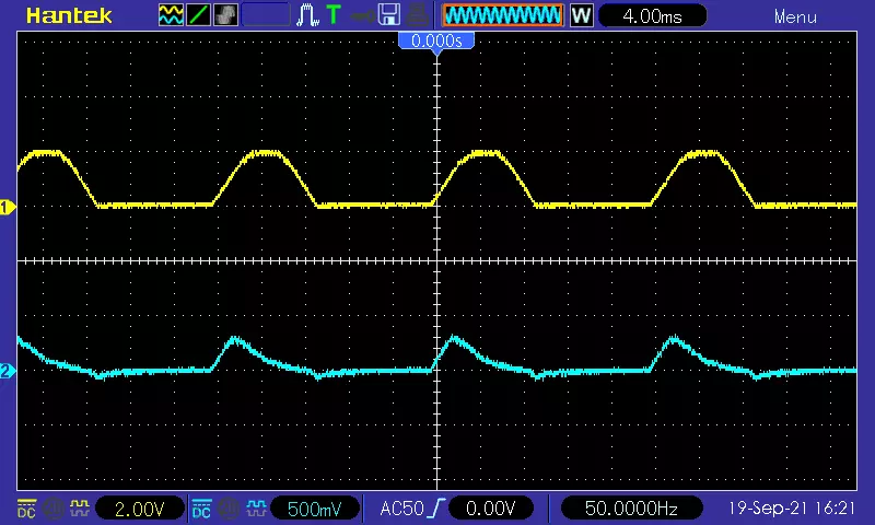
First, at about 22 A primary current. (20 turns @ 1.1 A)
The upper (yellow) trace is the voltage across a 0.33 Ω shunt, the lower (blue) trace the voltage across the c.t’s 10 Ω burden.
In each case, the zero level is marked by the arrows on the left-hand edge of the window.

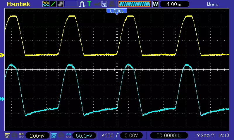
The “base” of the wave, which is a flat line at zero in the primary circuit has become a sloping line (because of the limited low-frequency response of the c.t. - see Measuring AC current output from a VFD - #18 by dBC) and it’s offset negatively so that the average over a cycle is zero - again because the c.t. blocks d.c.

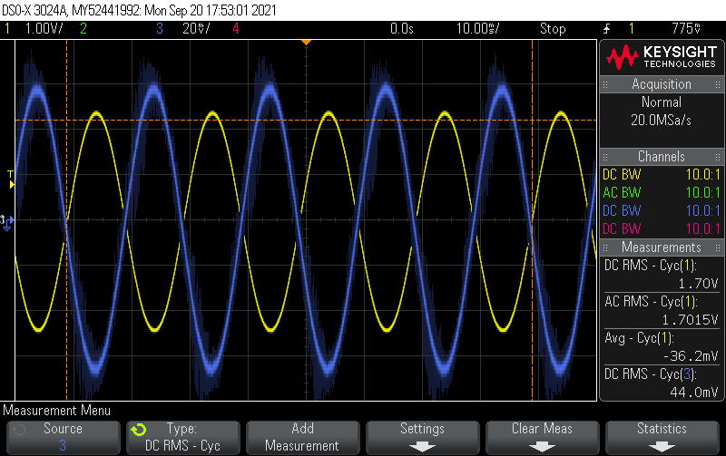
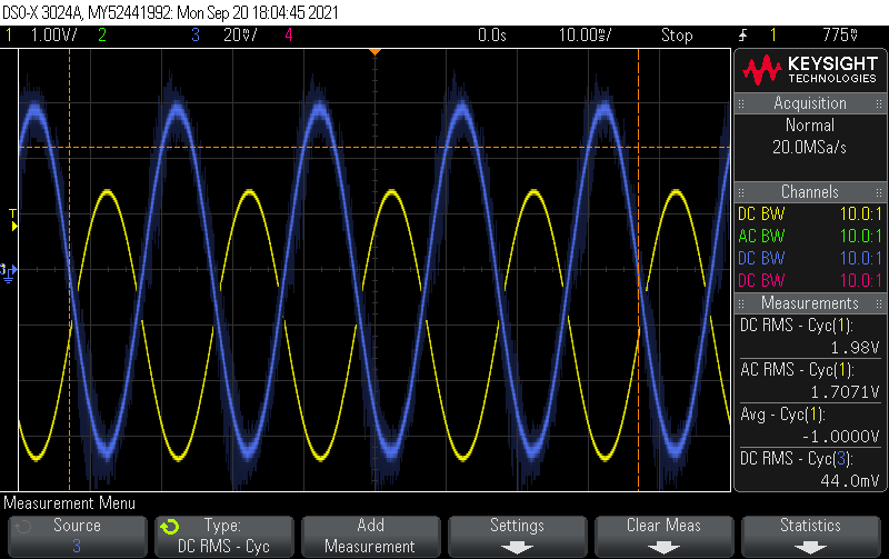
Here is the same c.t. at about 100 A - no rectifier:

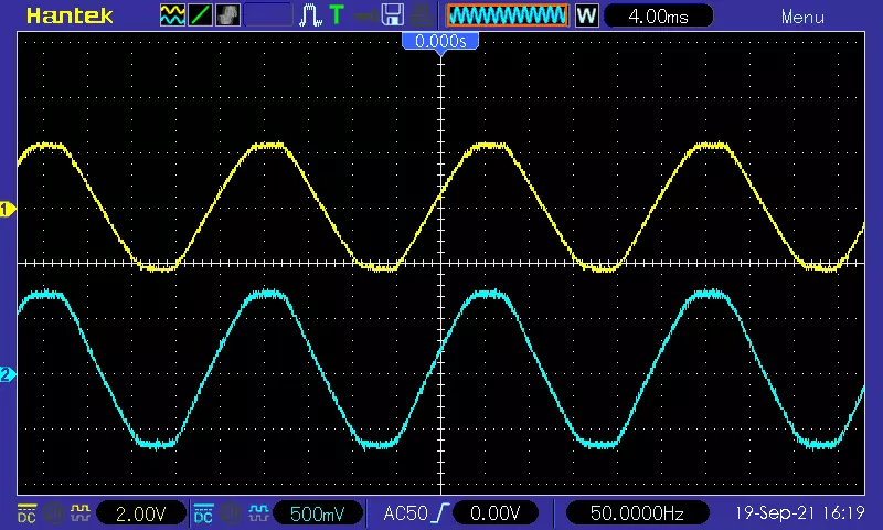
And with the rectifier, using the same scales, but slightly less current. It is not at all happy with that:

Had that been a steel core in the c.t. rather than ferrite, it would probably need demagnetising now to restore accuracy.

1 Like

Here’s an example from the test rig described in the thread referenced above. Yellow is the voltage across a small shunt in the primary circuit and Blue is the voltage out of the CT connected to a 22R burden.


Everything balanced around 0.


A DC offset added to the primary circuit (the Yellow trace pushed south by 1V).

What the scope calls “DC RMS” is really total RMS of the signal. “AC RMS” is the measurement of the sinewave with any DC offset removed. In the first pic they’re the same because there is no DC offset. In the second pic the sinewave is still 1.7V RMS, but the total RMS has jumped up to 1.98V because of the 1V DC offset. The other thing to note is that 12 + 1.72 = 1.982

So there’s considerably more work being done by Yellow signal in the second pic - things are getting hotter faster, but the Blue signal is identical between the two. The CT just thinks there’s 4A flowing in both cases, and remains nicely balanced around 0.

1 Like