I am using an YHDO-SCT013 100A/50mA CT with a 33Ω burden resistor connected to my Arduino at 5v.
I have connected an extension cored with the wires separated and clamped the CT onto the load wire. I used a Kill-A-Watt measurement device to check the current draw of an appliance to adjust the current calibration for emon1.current. However when I change the appliance to a different setting drawing more/less power, the readings on my Arduino and on my Kill-A-Watt no longer match up. The range of current in my testing is 9A - 13A.
I am unsure where I am making an error and what I can do to get correct readings as I have followed the CT guide in the Learn section.
What you might be seeing is the inherent inaccuracy of a current transformer at low currents. What you have there is a 100 A device that’s specified to have a 3% linearity between 10% and 120% of the rated current. In other words, the manufacturer won’t even give a value for the accuracy below 10 A. However, when I’ve measured a SCT-013-000, the output goes well below 9 A still with reasonable accuracy, so although you’ve given no details of how the readings don’t match up, I’d suspect the layout of your input circuit might be picking up noise, and you are in fact measuring electrical noise - possibly from the power supply you’re using - as well as the voltage across your burden resistor - which at 10 A primary current is 165 mV.
What you can do to improve the accuracy is use a multi-turn primary winding - pass the wire through the c.t. a number of times, up to 7 - and then divide the current reading by the number of turns through the c.t.
Be mindful that 7 turns carrying 13 A bunched together can get warm, so you should consider using thicker wire (possibly up to 2.5 mm²).
The calibration constant - I think you must be using emonLib - is the current that gives 1 V rms at your Arduino input. That’s easily calculated, it is 60.6 (or 20.2 if you have 3 turns for the primary winding). If you set that, does it read the correct current at full power (with due allowance for component tolerances) and with a “well-behaved” load?
I adjusted the calibration constant to 61 to match the 13.16A reading on the Kill-A-Watt meter with the hair dryer on hot high setting. Then when I switched the hair dryer to the hot low setting the meter read 9.26A while the Arduino read 5.95A.
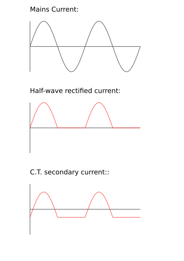
This is because the hair dryer is effectively working on direct current (the heating element is, the motor of course will not be, but that represent a tiny fraction of the overall current), but no transformer will pass direct current, therefore the half wave that passes through the rectifier diode gets shifted so that the average current is zero. emonLib still calculates the rms value correctly, but it is calculating the rms value of the shifted half-cycles from the c.t., not the unshifted wave. There’s little you can do about this safely, because for your safety, you must continue to use a transformer to isolate your Arduino from the mains electricity.
I passed the load wire through the CT four times, then divided the reading by 4. This along with @Robert.Wall 's explanation on why my hairdryer readings were so different between settings seems to have solved the problem I was having. I calibrated and tested using a fan and my soldering iron getting readings that look correct. I will do more testing later to verify further as the extension cord I am currently using to separate the load/neutral wires is not grounded.
A soldering iron isn’t a good test load because it’s likely too small, or possibly powered by
a switching mode power supply. (i.e. if it’s not heated directly by the mains)
The fan isn’t good because a motor is a reactive load.
The ideal load is a resistive load (there’s that damn toaster again!) like a space heater with a small (or better yet no motor) or any other device that uses a heating element that draws approximately the power you’ll likely be monitoring.
The FAQ addresses these issues as well as a couple more.
For my purposes I will only be interested in measuring current as the circuits I am interested in measuring carry more electricity than household mains power. I have found other current transformers that have current measurement ranges that fit my application. Is the burden resistor the only component of my setup that needs to be adjusted according the other CTs with higher measurement ranges?
Yes - for an Arduino running at 5 V, you should choose the burden so that, at the maximum current you are likely to want to measure, the voltage that the c.t. secondary current drops across the burden is not greater than 1.6 V. (This allows a small amount of headroom for component tolerances.)
But you should also bear in mind that a c.t. is at its most accurate when working into a short circuit, so increasing the burden value to increase the sensitivity comes at a cost of reduced accuracy at the lower end of the measuring range. In order of increasing preference, for increasing sensitivity you can (1) increase the value of the burden, (2) use a multi-turn primary, or (3) use a c.t that’s rated for the load. You must balance that against the need for 1.6 V across the burden to fully use the input range of the Arduino, unless instead of the 5 V supply, you use the internal 1 V reference and redesign your analogue bias circuit accordingly.
(I’ve added a diagram to my post above to show the waveforms.)
What would be the differences/advantages between using the 5V supply vs the internal 1V? Would the two setups offer similar measurement accuracies? I plan to specifically get CTs for each circuit based on amperage with the average reading toward the upper limit of the measurement range.
The principal advantage of using the (nominal) 1 V input is you have a very much wider choice of c.t.
As far as accuracy is concerned, you’re unlikely to notice the difference unless the c.t. you’re trying to force into generating 1.6 V is overloaded and distorts the wave shape. If you look in the Learn section at the test reports on the two c.t’s that the OEM Shop sells, you’ll see how the errors increase when using a high value burden (as in the emonTx high sensitivity input), and especially how the SCT016 fails completely to reach its rated maximum current.
You might run into trouble with:
You should rate the c.t. and the input for the maximum current that you’re likely to want to measure. If you have appliances that demand a high inrush current – induction motors in refrigerators are common examples – you must take that into consideration too.