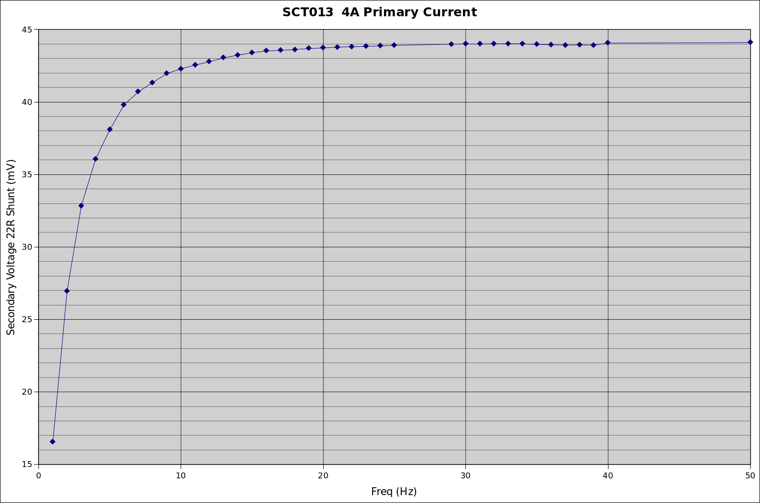
My take on that is you can measure the roll-off at any old current, because it happens somewhat independently of saturation. My calibrator can do some big currents, but only in the 45-400 Hz range. But my signal generator can go all the way down to DC, so I fed that through a 2-quadrant amplifier followed by a few loops through the CT and managed 4A RMS of arbitrary waveform and frequency through the CT. My Fluke TrueRMS meter is only good down to 45Hz, so I used the scope to measure the RMS values from 400Hz down to 1Hz.
Basically, a whole series of captures like these:
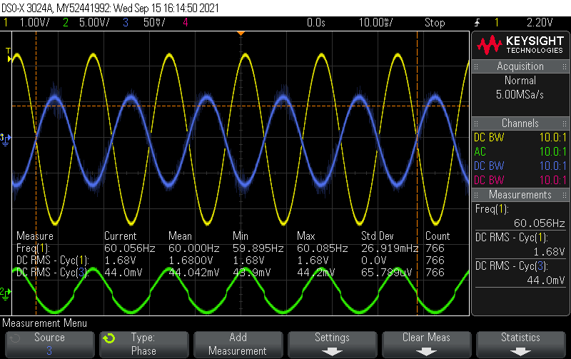
60Hz
…
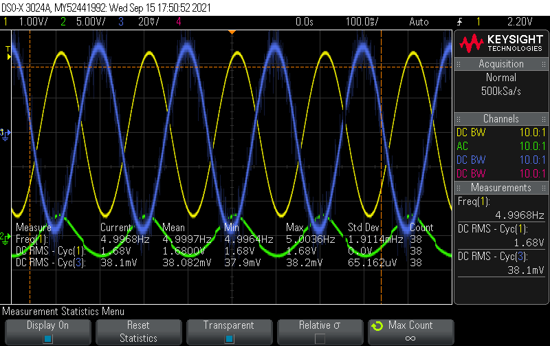
5Hz
Yellow is the voltage across a small shunt on the primary circuit, just to ensure things were stable.
Blue is the output of an SCT013 feeding a 22R burden.
Green is a signal on the amplifier for monitoring it’s performance and can be ignored.
There was a hint of distortion at 2Hz and …
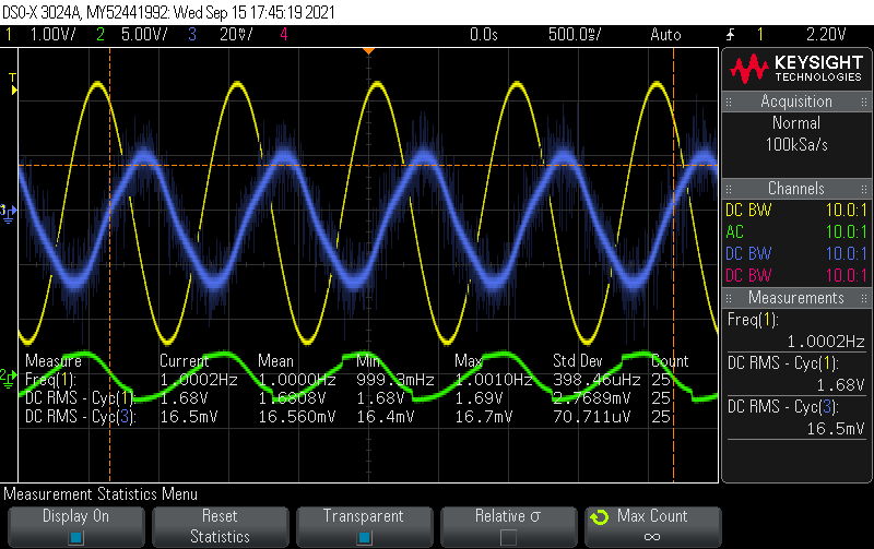
a definite kink at 1Hz (as well as some serious phase shift), but higher than that it looked very clean.
Here’s how the readings look plotted (I truncated the graph at 50Hz to give a better view of the lower frequencies.. it was flat line all the way from 50 to 400):