Samsung heat pump defrost frequency

Hi,

I have also been on a steep learning curve about Heat Pumps.
My "installation " was started on first July , and , as of 20 th December has still not been completed.

My latest lesson concerns De-icing on my Samsung 5Kw Heat pump.
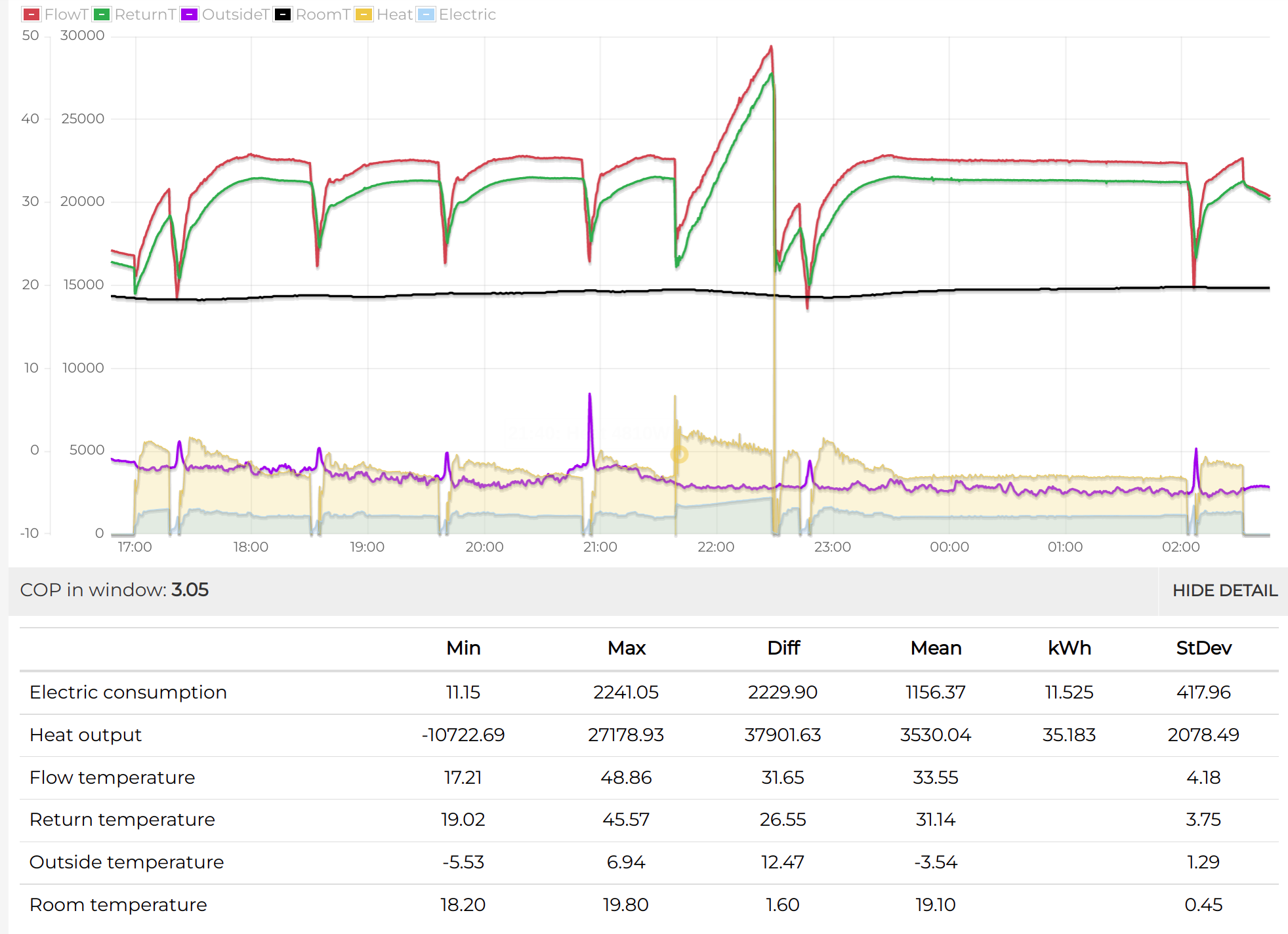
The outside Temperature , at night plunged to -8 C each night between 15th and 19th December with the heat pump responding with innumerable warning messages that my “Energy Consumption was excessive.”

The Energy was being consumed by the de-icing routine on the Samsung Heat Pump when heating the Fins of the Heat Pump. The Samsung emitted large quantities of steam!

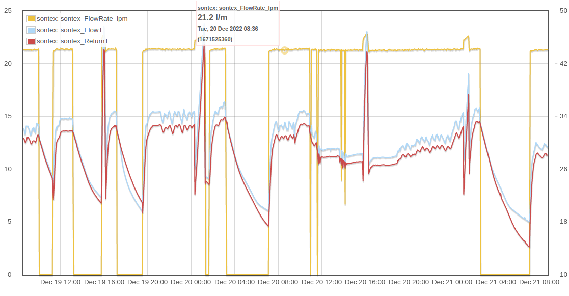
I installed a home made Power meter using a CT transformer which revealed a staggering 25-30 de-icing calls each night between the 15th and 19th December.

The resulting astonishing graph was obtained from my home made Arduino Power / Energy meter.

My neighbour commented with concern about the large volumes of steam being emitted during these de-icing episodes.

I have reduced the hot water tank tank temperatures from 50 C to 25 C to try and limit the electricity bill.

My morning room temperature was reduced to less than 12 C on each morning.

yours

A Cold , Broke, former Heat Pump enthusiast!

power_Dec_15-19.pdf (33.8 KB)

Is this using a built-in heating element, rather than borrowing heat from the central heating system? Most recent installs I’ve seen rely solely on heat from the house to defrost, which doesn’t use much extra power. Perhaps there’s a setting on the heat pump to change how it defrosts? Maybe ask your installer?

It’s quite normal to see some water vapour rising from the unit during defrost cycles (it’s not steam).

This does seem a bit much - once per hour seems more typical. What is your flow temperature set to? You’d be better off lowering that instead of your hot water or room thermostat.

The power consumption on your graph doesn’t seem particularly high though, about what I’d expect for a 5kW heat pump. What’s the cumulative kWh per day like?

See Glyn’s Heat Pump data for comparison, which is also a Samsung 5 kW.

There’s another thread of Samsung heat pump owners that might be useful to you: Samsung Gen 6 8kW Efficiency

@glyn.hudson might be able to advise on the defrosts you’re seeing.

Can you post a graph of say 12 hours? It’s hard to see the frequency of the cycles on the previous graph.

Hi Tim,

Many thanks for your swift , and insightful response.

My Installer:

My “installer” initially started the Samsung Heat pump on 1st July without fitting five major components.

Each of the five missing components have been fitted over the last six months.

I have, unsurprisingly, no confidence in the installer.

Additional Freezing Protection:

My Samsung Heat Pump is somewhat unusual in being fitted with a Heat Exchanger dividing the pipe circuit into two separate water circuits.

Heat is transferred from the Heat pump located in my garden, to the primary ports of the Heat Exchanger . This primary pipe loop only has a volume of 6 litres.

Samsung require a minimum pipe volume of at least 20 litres to avoid both Cycling and increase the volume of water as a protection against frost.

Samsung advised , in November, that a 50 litre Volumising tank be fitted across the primary inlets to the Heat Exchanger.

My installer fitted the 50 litre tank in October.

At a water flow temperature of 35C a 50 litre tank would hold 504.335 = 7500 Joules as a protection against frost.

The 50 litre tank also, incidentally , smoothed out the cycling that became very apparent in September and October.

Given the large energy usage and the large clouds of white Vapour/Steam I seem to have both an Electrically heated de-icer element and a 7500 Joule tank storage.

None of the Samsung "field controls " adjust any of the control parameters for the de-icing circuits.

Water flow Temperature:

The Water Flow temperature on my Samsung Heat Pump is controlled by an offset to the Water law.

I have adjusted the Water Flow temperature to adjust the power consumption for optimal radiator performance at optimal Economy…

I have adjusted both the Water Law graphical settings using the Field controls and used the Water Law offset Display control.

No such setting affects the de-icing performance.

Additional Graphs of power and energy:

Please find attached graphs of both power and energy showing a closer view of the power ( Kw) and energy (Wh)

Again many thanks

Scotland can get very cold!

iantelescope
power_Dec_6_7.pdf (14.9 KB)
Energy_07-Sep-2022.pdf (25.3 KB)
power_Dec_5_6_.pdf (14.6 KB)

1 Like

Oh dear, sorry to hear you’re having issues. Here’s the data from my Samsung Gen6 5kW at -5.5C. It’s defrosting once very 70min or so and having no issues providing heat.

The defrost only takes about 5min to complete and doest seem to have any effect on the roomT

I’m running quite a low flowT for 35C which probably means my unit is defrosting less than if I was running a higher flowT. I think in your case the defrosting is a symptom rather than the issue. What flowT are you running? Maybe your emitters are undersized? I’m only using radiators, but they are quite large double panels ones. Has your unit got plenty of air flow?

Here’s live data from my unit: Emoncms - app view dashboard

Here’s a video of my ASHP installation retrofit:

Samsung gen 6 doesn’t have a heating element, at least mine doesn’t.

If the unit is only heating your house to 12C that’s not good, you should get in contact with your installer. They have MCS obligation to make the system preform as per the MCS quote and calculations they will have made before the installation.

2 Likes

You can just paste the images into a post (Ctl-V). Attached files are less useful.

Hi Tim,

Again many thanks for your help …and patience!

My installer is incompetent having been “struck off” by the NIC and the RECC.

Could I ask for your comments on the unique system I have:

A: The Heat Exchanger:
I have two pipe water circuits:

  1. From the Heat Pump, in my garden, to the input ports of a Heat Exchanger.The "Primary "water loop.
  2. From the output ports of the heat exchanger to the Radiator circuit.The “Secondary Water loop”.

The Heat exchanger successfully isolates the Primary Water loop from changes in Water flow and pressure on the Secondary Water loop. A perfect Water Transformer.
Heat is however efficiently transferred from the Heat pump to the Secondary Circuit.

B: Volumising tank:
A 50 litre Volumiser tank has been fitted across the input ports of the heat Exchanger to:

  1. Smooth out the “Cycling , or pulsing” that occurs when the Heat Pump reaches the bottom of it’s power linear control, about 25% of the maximum power from the Heat pump power control.

The MCS provides an example of how to calculate the required volume of tank.
By my calculation, I would require a 35 Litres volumising tank.
Samsung and Telford , the manufacturers , asked for, and got, a 50 Litre tank fitted in late October.

  1. A 50 litre Volumising tank operating at a water flow temperature of 35 C would store

Energy Stored in 50Ltr Tank = 50 x 35 x 4.3 = 7500 Joules.

This 7500 Joules of energy is used to provide heat during de-icing.

Could ask a further question:

Over what period do you calculate the RMS AC current taken by the Heat Pump?

I use a 10 second integration/averaging period , clearly showing the power consumption in far greater detail than is provided by your Current ,Power and Energy graphs.

Yours
iantelescope

1 Like

This might actually be a “low loss header”, which is a common way for heat pumps to provide hydraulic separation between their main circuit and the central heating system. Does the same job of heat exchange, except the hot water from the heat pump goes to the radiators and back.

Either way, you only want the heat pump to be running when the central heating system is circulating, otherwise you’re just using energy to keep the volumiser warm unnecessarily.

A volumiser (or buffer) does exactly as you described: smooth out cycling and provide energy for defrosts. Many installers would try to design a system that doesn’t need one, instead relying on the central heating circuit having enough volume to keep the heat pump running well. There are circumstances where it can be necessary though.

It’s generally advised to keep the central heating system as “open” as possible, i.e. with radiators turned up to full, and reducing the flow temperature of the water coming from the heat pump. This ensures that the heat being generated gets put into the house rather than going back to the heat pump, and reduces the need for a volumiser.

For more about monitoring, see Heat Pump Monitoring — OpenEnergyMonitor 0.0.1 documentation

Hi Tim,

Again you seem to understand, and have experience of , a lot more than my “installer”.

My Samsung /Telford Heat was clearly not designed by my “installer”.

The Heat pump was initially “installed”, (and switched on !) without a water flow meter, Expansion vessel, PRV,Volumising tank or Energy meters.

My Samsung was , probably, initially “designed” for a dual 5kw system with a common pipe system.
The Heat Exchangers were probably used to isolate the Heat Pumps from the common pipe work.
Every “Spare part” was supplied in pairs but not initially fitted.

My Heat Exchanger is a modern day replacement for the buffer tank used to remove Cycling when heat pump power variation were controlled by Pulse Width Modulation.

Modern Heat Pumps output heat power linearly over a 25% to 100% range on the maximum power.
However, when output is required at 25% and 100% the system reverts to effectively Pulse Width Modulation or Cycling.

A volumising tank is required to smooth the Cycling ( pulsing) at 25% of Maximum power during Spring and Autumn.

The heat power demand , or Water Flow Temperature, is here set by the Water Law graphs and the Water Law offset Display controls.

The volumising tank is also used as a store for the Heat Energy used for de-icing.

The volumising tank does , in normal circumstances store circa 7500 Joules with a further power loss of 25Watts.

No Field controls on the Samsung cover the control of the de-icing power usage.

No Field controls on the Samsung cover the control the “Volumising tank.”

The “Special Energy Saving” controls only reduce the Hot water tank Temperature.

iantelescope

1 Like

Hi Tim,

My Samsung comes with two Grundfoss UPM3 Flex motors , one on the Primary , the other on the Secondary (Radiator) Circuit.

The Grundfoss motors are complete with PWM motor controls , as does the Samsung Control board.

The Motors are , however, not connected to the control board.

Given the efficiency improvement in using PWM should I connect the PWM motors to the PWM outputs on the Samsung Control board?

iantelescope

We had been running low flowT but had to put it back with sub-zero temperatures.
Our Samsung AE160RXYDEG 16kW HP was defrosting every 50-60 minutes with flowT 45c and outsideT -6c. Power consumption during defrost about 1kW.

I’ve got my UPM3 pump connected via PWM, but Samsung doesn’t seem to modulate the pump speed, therefore if the pump seed is set correctly I don’t think you’re missing out on any efficiency e.g as you can see flow rate is constant, it only increases slightly during DHW, but I think this is due to the lower pressure of the DHW coil compared with CH rather than any change in PWM:

However, you should check that the pump stops running soon after the ASHP compressor stops, some ASHPs run the pump for a long time after which is a waste of energy can cause excess heatloss circulating warm central heating water to the outside unit.

That sounds normal, what you would expect from a system that’s working well.

1 Like

Hi ,

Again many thanks to Glyn and Christian. You have answered some of the many questions I have with my Heat Pump.

To limit the energy consumption I have tried to run my Heat Pump at between 32 C to 35 C.

I set the 32-35 C band by initially reducing the Water Law controls to -3 C.

When the outside temperature fell to an estimated -8 , I increased the Water Flow Temperature , again using the Water Law Control, eventually reaching a +4. Water Law setting.

I then increased the Field parameters 2020 to 45 C and 2030 to 50 C . To bring the Room temperature up from hypothermia at 12 C in my living room.

The Water Law offset Display setting was then reduced to 0 C.

The Heat Pump continued emitted large clouds of White Vapour/Steam during the nights.

The Heat Pump issued innumerable complaints that it had exceeded it’s Dailly and Weekly Energy quota of 21 Kwh.

The Heat pump has now, 22 Dec returned to a normal operating condition as shown on the attached graphs.

Power Graph:
The Power graph shows that the Heat is still switching ON and OFF repeatedly through the night.
The massive peak in power is caused by the “Legionella” disinfection routine set for the evening at 23 00 …
Energy Graph:
The Energy graph shows that although the Heat is violently switching ON and OFF the Energy consumed is relatively small at ~2 Kwh.

DeltaT (HPout-HPRet) Graph:
Shows the Delta T across the Heat Pump itself:

DeltaT RadOut-RadRet Graph:
Shows the DElat T across the Secondary , Radiator Water loop.

The Temperature graphs were obtained using Four K type Sensors which are , again very sensitive.
The K type sensors are clamped externally on to the pipes so the absolute Temperatures differ from that displayed on the Control Console by about 2 C.

The External sensors can only be used as a measure of DeltaT given that All the sensors are connected to a common copper pipework.

Again many thanks in my struggle with this , my hypothermia machine.

Outstanding Questions:

How do I interrogate the Heat Pump itself?

Do I need to fit a B19N Samsung to Mod-bus rs485 converter to interrogate the Heat Pump?

Can I get the correct pipe water Temperatures other than by breaking into the copper pipes themselves?

Why is my Heat Pump Violently oscillating through the night?

iantelescope

power.pdf (25.1 KB)
energy.pdf (22.7 KB)
Delta_T (HPout-HPRet).pdf (19.9 KB)
DeltaT RadOut-RadRet.pdf (20.3 KB)

Hi Glyn:

I have been comparing your Water Flow temperature results with my own results.

Your DeltaT:

                Output /water -Temp - Return Water Temperature  >  0 at all times

My Primary DeltaT:

Primary Water Loop Water output Temp - Primary Return Water Temperature < 0 at night.

My Secondary (Radiator) DeltaT:

Secondary Output Water Temp - Secondary Return Water Temp < -4 at night.

My Heat Pump is taking the 7500 Joules of Energy stored in the 50 Ltr Volumising tank to keep itself warm during the cold nights!

The Heat pump , in keeping itself warm , is cooling my house by < -5 C !

Little Wonder that my morning Room Temperature is circa 12 C!

The Heat pump is more concerned with de-icing itself than with my hypothermia.

Poor wee cauld beastie!

Delta_T (HPout-HPRet).pdf (19.9 KB)
DeltaT RadOut-RadRet.pdf (20.3 KB)

Hi glyn,

Again many thanks for your advice about the PWM control of the Grundfoss Motors on Samsung Heat Pumps. I will not fit the PWM controls until a later date.

My Samsung being fitted with a 50 ltr “Volumiser tank” at a water flow temperature of 45 C used during the recent cold spell the tank would store :

Energy Joules stored in Volumiser tank for de-icing = 50 X 4.3 X 45 = 9600 KJ

I am consuming 2 kwh of electricity per night for Electrical de-icing = 2 X 60 X 60 = 7200 KJ

The total Energy consumed for de-icing is therefore 16800 KJ = 16.8 MJ

Is 16.8 MJ per night excessive? How to reduce this?

The Electrical Energy consumption has a using a constant amplitude and Pulse width but varies the power by changing the frequency.

Is the Electrical heating Pulse Density Modulation?

How do I fit a B19N Modbus RS485 to Samsung Converter.when my Samsung does not have a recess to mount a B19N ?

My Samsung still has the connectors F1 F3 ,RS485 A&B and DC power but no space to mount the B19N.

iantelescope