I don’t run WL I set the flow temp via modbus (this might effect what happens)
But I can’t get my Gen 7 R290 16 kW to its lowest modulation state unless I slow the flow rate down. If I go fixed speed, it will just keep the compressor going hard then then turn off due to exceeding heating target. Its really stupid
I’ve seen a few industry insiders comment on the origin of dT 5C in ASHPs, and implied it is a pretty arbitrary value.
Maybe we should think more in terms of dT being less than or equal to 5C, and not 10-20C as per gas boilers, rather than chasing a mythical 5.0degC.
If the emitters are unable to emit the heat produced, then dT will narrow which will ultimately cause the LWT to rise to the point where the emitters can emit said heat (or the heat pump will cycle to try to maintain the target LWT)
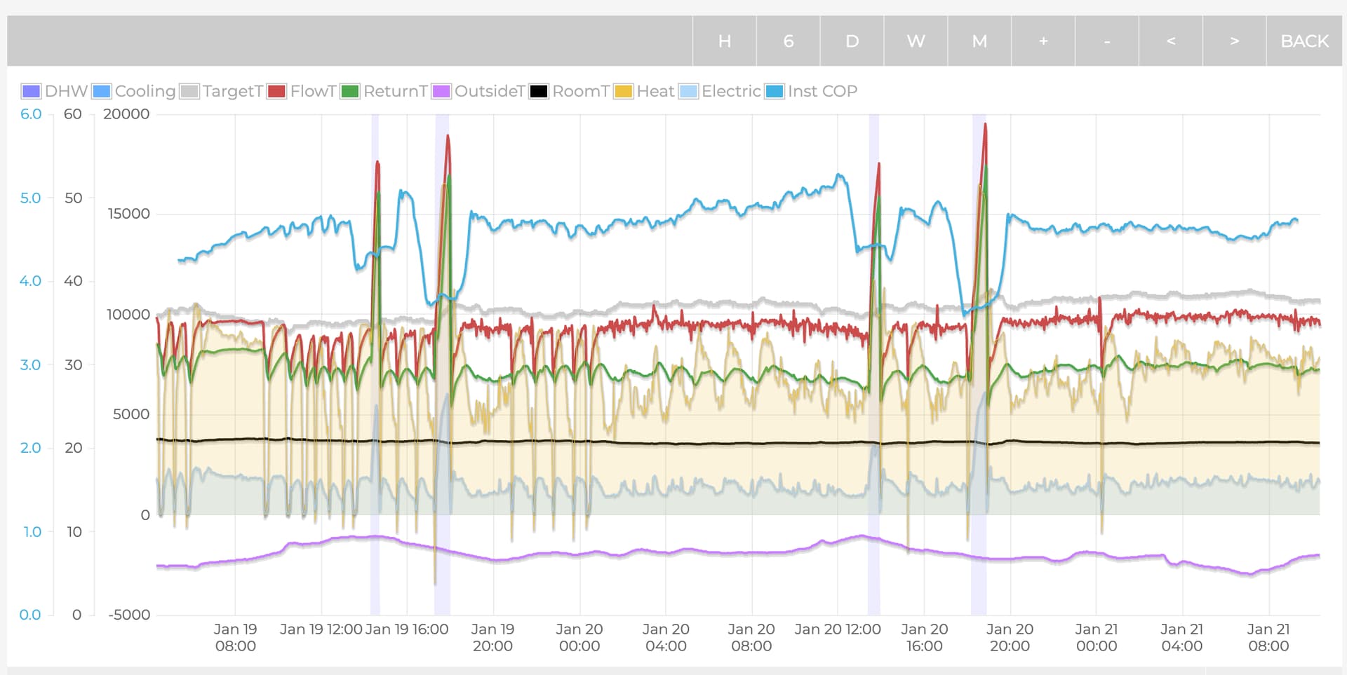
When running in “always on” mode (#2091=1), if LWT is set unrealistically low, this is what will happen. For any given outside air temp, the system will find it’s own equilibrium where the heat being produced can be dissipated by the attached emitters. On my system, this tends to occur at a LWT of around 31-33C (depending on OAT, and hence COP - the warmer it is, the more heat that is produced for a given electrical input, and the higher the LWT must be for a fixed size emitter system to dissipate that heat) at a LWT-RWT dT of around 3C. These observed data match well with the minimum heat output for my heat pump and the heat output of my emitter system at said flow temps. I’m no longer concerned that at this steady state of operation that dT is not 5C, and hence am not concerned with running PWM variable flow rates.
I have two pumps in series (needed to get up to 40lpm), the curve of flow rate to power is really bad at the top end, so having the pump modulate down when it’s not needed is great!
The second pump has ESP32 that controls the pump speed (Ive done this as I have a hybrid system, so sometimes I need the second pump to run when the heat pump is off)
Before it was emulating what the heat pump was requesting, but I added a dampener to it, only allowing a rate of change of 1% per 10s. That was it.
With this logic it seems a lower control factor FSV4053 would help, however I run into a second issue where the logic does not slow the pump down fast enough that we cycle before it gets to a point where its balancing things correctly.
The last annoying thing I have noticed is every so often the heat pump will just run PWM at 100% and ignore everything. In these cases when the unit cycles and the flow rate goes to 0, I turn the heat demand off for 2m which seems to reset the pwm. I really need to email samsung to ask what is going on
Certainly doesn’t sound correct (something lost in translation maybe?). I don’t have a PWM pump connected, but I can see the value step down to 25% in the controller once I’ve reached LWT, and my LWT is set at 32C.
Would you be able to share a few more details of your MIM PWM controller? The Grunfos pumps spec a 5V PWM waveform. Did you use a logic converter, or did you find 3.3v was ok?