Installed in September. I’ve convinced myself that not all is well. No monitoring hardware - my installer thought it a waste of money. Looking at the wired console data I’ve recorded the following:
Power 0.6kW WO 32.4 Flow 16.5 Inverter 86% Teva_in 30 Tw1 29 Tw2 32
Power 1.1kW WO 34.5 Flow 16.5 Inverter 86% Teva_in 25 Tw1 33 Tw2 34
Power 0.5kW WO 34.2 Flow 8.8 Inverter 51% Teva_in 27 Tw1 28 Tw2 33
Power 0.6kW WO 32.8 Flow 17.3 Inverter 98% Teva_in 30 Tw1 29 Tw2 32
Power 0.6kW WO 32.4 Flow 16.5 Inverter 98% Teva_in 30 Tw1 29 Tw2 32
Power 1.3kW WO 32.0 Flow 17.5 Inverter 100% Teva_in 29 Tw1 27 Tw2 32
Power 1.7kW WO 31.7 Flow 17.5 Inverter 100% Teva_in 27 Tw1 23 Tw2 30
Power 0.7kW WO 34.2 Flow 12.5 Inverter 69% Teva_in 31 Tw1 30 Tw2 34
Power 0.7kW WO 34.8 Flow 17.9 Inverter 100% Teva_in 20 Tw1 31 Tw2 32
Power 0.7kW WO 34.6 Flow 14.5 Inverter 77% Teva_in 30 Tw1 31 Tw2 34
The Teva_out is always -50, the EEVStep is always 0 (whatever it is …)
So the Delta T (Tw2 - Tw1) seems to be all over the place. Hit the magic 5 once. I have been using a EliTech temperature logger to monitor the flow and return temperatures, typically only one or two degrees over a number of days.
To me it looks as though the primary control loop is being limited.
About the system. Four heat loss surveys, me, Octopus, Heat Geeks and a ‘surveyor’ commissioned by my installer. I ended up upgrading 9 out of the 11 rads myself. As for the pipework no one looked at it. However I’ve since looked at it in more detail - 22mm copper and 15 to the rads. So there shouldn’t be a problem there. However my ‘installer’ used Kaiflex 2in2 pipe from the HP to the diverter valve and then 12m to the existing radiator pipework. The Kaiflex pipe has an internal diameter of 25.4mm but it is corrugated (3.2 mm corrugations 5mm apart). In practice this means that it has 3 times greater resistance (pressure loss) compared to 28mm copper. There is also a 25l ‘volumiser’, Y magnetic strainer, 3 port valve, 28mm flushing and flow limiter plus all the isolation valves to consider when it comes to pressure loss.
Another problem I’ve noticed is that the HP power goes up to 3.2kW during a frost/defrost operation. It also gets a bit noisy - 72dB. Whether that power is during the ‘frosting stage’ or actual de-frost I’m not sure. Is that normal? It’s an 8kW unit by the way.
I have spoken to Samsung HP support - helpfull but his last words were ‘speak to your installer’. Installer - neat, tidy, no tea or coffee but only one of them seems to know anything about Samsung Heat pumps. His attitude is ‘don’t touch anything’. I have tried three other Samsung accredited installers - no reply. Samsung themselves want £550 + VAT + travelling expenses for a site visit.
Any advice?
I think you’ll get yourself in a muddle without proper monitoring equipment and may end up chasing your own tail.
The Samsungs flow temp fluctuates a degree or two every few minutes (but on average it will be around at around the target flow temp) so depending on when you’re measuring and how frequently, you’re unlikely to be getting an accurate picture of the flow temps.
They also tend to ramp down the flow rate quite slowly, and only start ramping down after 20 minutes. It also takes a long time for the freturn temp to come up to temperature (about 90 mins in my case, but my PWM currently isn’t working so that will be longer than if it were). You really need a long extended, uninterrupted run at constant outdoor temperature with no cycling and to take reading much more regularly to even come close to trying to determine if actual DT is matching target DT.
I also have gen.7 R32. What is BEK variant ? Is is R290 >
In any case I don’t have such behavior. I assume you have a monoblok right ? Monobloks use heat from the flowing water to do a defrost so this is an advantage over a monoblok. During this time the outdoor FAN is stopped.
This pump defrosts not that often from what I’ve seen but depends on weather condition and compressor speed.
It lasts about 4 - 5 minutes and during that time compressor input is maybe 400W so not 3.2kw as with your pump. This might be different if you have split heat pump though.
@Michal_S
I have the Gen 7 5kW BEK/EU version, in R290 version. and when it enters defrosting, I’m only consuming 150W. I’ve run through the datasheet and it says the base heater is a 150W resistor, so everything if coherent.I’ve not checked the base heater power for your variant.
Cheers
I self installed a gen 7, 8kw Samsung integrated just over a month ago with full monitoring which I am still really learning about. From your figures (William2) Ive got similar results on the delta T i.e. it rarely manages the magic 5c its set to and I’m not sure why because it occasionally does but only when I have under floor heating coming on as well as the rads. So is it a loading issue, or needs more volume or is it that the HP cannot reduce its output enough I’m not sure, perhaps someone can comment with a suggestion. Samsung don’t know either?
My piping loss is quite high at 10.5m + elbow; fittings and valves so have added an extra pump in series and get a total of 17-20lpmin flow with both pumps. At the request of Samsung tech I got it to up 26-27lpmin with an additional pump but made no difference so back to 2 pumps, integrated does about 8lpm, additional 10-12lpm. The integrated pump does pwm down but suspect it’s not enough to throttle the output back enough as the output as the second pump is fixed and no option from the HP to PWM a second pump.
The defrost cycle also seems to take a lot of energy and happens very regularly when its lightly loaded so I don’t think its defrost, perhaps just turning off?. Heather posted a feasible explanation for this which I put to Samsun technical but heard nothing.
Mine stopped the other night with a 536 fault which is a refrigerant leak. Put this to Samsung technical but was met with the same “£550 up front before we will look” Decided not to do anything as its unlikely any fault would be found as working as before as far as I can see. Agreed, on lack of knowledgeable people for this HP, also any monitoring to see whets going on perhaps too new and then there’s the dreadful indoor unit? This is what I mean.
I’ll hook up the Elitech again with a 2min sample period on the heating flow and return. I’ll also connect the Shelly EM to look at the power during defrosts. I’ll also complete the pressure loss estimates - just to see if I have to replace the Kaiflex pipe. I suspect that the low flow rates are part of the problem - the 8kW unit requires 26 lpm to give the full 8kW of power.
Teva_out stuck at -50. Would that be the boiling point of Propane? As for the EEV step = 0 - no idea what the ‘EEV’ is.
Peter - your heat output in the above graph - and the rest look a bit suspicious - why the oscillations?
William2 I’ve real clues nor it seems have Samsung who have seen the pics and have also been sent the dashboard link as well. They sent me a new flow sensor FOC which I have changed with no difference as far as I can see. They initially cast doubt on the accuracy of the openenergy setup, perhaps they were not aware that anythng so comprehensive existed?
The HP sensor is currently 27.9lpm and openenergy 19.78lpm, currently on DHW and 3202w in and 7350w heat
If your pumps are not able to modulate via PWM you’ll only see DT when your heat pump is able to output 8kW and your emitters are able to output 8kW. Samsung uses pump PWM to slow down the flow rate to target DT5 (or whatever your DT FSV is set to).,
In my experience with Samsung, is that they work a lot better when PWM is functional. Having two pumps in series running at different flow rates is not a good idea since they will fight each other. In your installation I would have through that adding hydraulic separation with a buffer or LLH would be beneficial if the secondary pump is required if pipework upgrade is not possible.
Therefore, the 8kW unit is quite oversized. The minimum modulation of an 8kW heat pump is about 3.2kW, therefore you’re unlikely to archive steady state running if the outdoor temperature is higher than about -2C or -1C.
Since the heat pump is 220% oversized you’ll be struggling to get enough emitter area to dissipate the heat, I would try and ensure that all the radiators and all UFH zones are always open to give the heat pump the best chance at dissipating its minimum output. If the heat pump can’t dissipate its minimum output, it has no choice other than to cycle on/off.
It’s a mystery why it’s defrosting so often, though, and the carnot efficiency is very low. Maybe it is low on refrigerant? Oversized heat pump usually hardly ever defrost since the amount of energy being extracted is very small compared to the size of the evaporator.
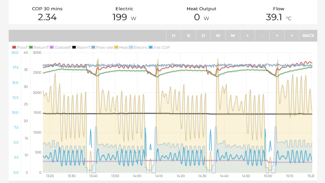
Update: looking more closely at the data, I don’t think is defrosting that often, what looks like a defrost is actually just the HP switching off. See the screenshot below, there’s only two actual defrosts when it gets cold. It’s just cycling at lot because of the oversized unit. There’s not much you can do about this.
Many thanks for interoperating the data and responding promptly. All sounds logical. We thought that we would try the system in as simple a form as possible (as per many recommendations) to basically see how it performs and get some data which we have done and it raises lots of questions. We are able to add a buffer as we have a 70l tank spare which can be connected in with a bit of pipe work juggling to give a comparison .
Before we bought the Samsung we had considered using a Grant ASHP. As they offer a free heat loss survey we sent all our house dimensions and construction details to them and they came back with a heat loss of 7519w for our 145m3 property. We had previously estimated the loss to be 6750w using some online guides so we chose the 8kw unit as being the nearest to these figures.
This is not really your fault, heat loss calculations using default assumptions always overestimate heat loss, often by a very significant amount. There are lots of reasons for this, but it’s basically worse case pessimistic assumptions built upon unrealistic worse case assumptions.
Many of the installers on heatpumpmonitor are aware of this, and adjust the default assumptions accordingly. Air charge rate (ACH) is a big source of the error: This is something we’ve looked into in detail: Air change rate calculation methods — OpenEnergyMonitor 0.0.1 documentation. We’re currently in discussion with CIBSE to try and get the default ACH figures revised.
A useful sanity check for a heat loss, is to take your historic annual gas consumption in kWh and divide by 2900 to give an approximate heat loss in kW. What Size Heat Pump Do I Need? A Rule of Thumb | Protons for Breakfast. Out of interest, do you have any historic gas consumption?
If I was being cynical, there’s no incentive for a manufacturer to put effort into speccing a smaller heat pump since they will make more money selling a larger one.
Thanks for the reply, yes everything always seems to be too large. Assume you got our property right for your calc? Our calcs came out at around 6kw loss. Yes realise that is difficult to get an accurate calc of heat loss no matter how you do it an actual measurement must be the way forward…too late for me now!
Do not have an annual gas consumption as we have never had gas, it was originally oil, worked great but cost a bomb, I installed my first HP in 2008 and the Samsung is HP no 3. We built the place starting 1998 and its UF everywhere which is still intact and usable on hard floors although it was designed for 60-70c. I’ve got some of the UF in use but carpeted wooden floors don’t work at these low temps and I didn’t want to tear the place apart to install pipes so the rads we recently added are fed from drops from the loft hence the high resistance and probably the root of our problems.
The Samsung is recording 27.3lper min at 80%pwm and openenergy 17.85lpermin so I’m assuming the OEM reading is accurate and correct?
This morning it looks like it’s trying to PWM down further but cannot because of the fixed second pump so having got some data of direct connection I intend replumbing to include the buffer tank and see what it looks like then. Shame no PWM easy connect for the second pump from Samsung.
Before I add a buffer did some searching on the forum and found a reference that converting from 4 pipe buffer to 3 pipe buffer made a big improvement to efficiency so it sounded attractive.
Cannot find much more but wonder if anyone has experience of this?
Works for me and it was fairly trivial to change to (from four connections). Definitely improved the performance. The question I guess is whether I needed a buffer in the first place but I suspect I do.
I’m fairly heretical in that I run two zones with Mitsubishi auto adaptation and TRVs on every emitter / radiator apart from the rooms the wireless Mitsubishi sensors reside. The idea of the temperature of your house being only controlled by the weather outside is not something I’m willing to spend effort on making it work because at best it’s a compromise.
Yes, the heat meter is Class 2 i.e 2% accuracy. This will be more accurate than the Samsung readings.
I would say that it’s probably unlikely to have a significant effect. In most cases the performance of a system, is resultant of the whole system design rather than a single component. Unfortunately, there’s no easy way to deal with an oversized heat pump. Adding more emitter area i.e larger rads and more volume (buffer or volumiser) will certainly help, and possibly upgrading pipework. Although whether the cost of the these changes would be worthwhile in terms of electricity savings is another question…
The most cost-effective way to run and oversized heat pump is to treat it more like a gas boiler, running it at higher temperature for shorter periods. I would experiment, setting your minimum flow temperature to about 38C. A higher flow temperature will allow your emitters to dissipate more heat which allows the heat pump to have longer run times, which counterintuitively should result in higher COP
Your HP gets decent performance when running longer at a higher flow temperature:
The only difference is that last thursday I cleared the leaves & rubbish from behind the HP after the ‘little wind’. Noticed that the external temperature sensor was touching the casing, so I moved it. Has anyone got a diagram of where the sensors are (or should be). Are they covered in thermal grease?
After a (very) little thought - there are two basic control loops involved. They are linked by the plate heat exchanger in the unit. One side is basically the compressor and evaporator. It tries to deliver the required heat for a given water outlet temperature. It depends on the outside temp - look at the power required for a given outlet temp and the outside temp. The other bit is how quickly the system moves the heat from the heat exchanger - I assume it adjust the flow velocity to reach the target Delta T. All sensors need to be accurate for the HP to function correctly.
Hi Peter, this minimum modulation seems to match my own observations. I measured approximately 2.2KW. Mine is the 8 KW DEK variant, and I think they use the same compressor.
I have a small discrepancy between my Axoima heat meter and my Samsung flow meter, but only arond 0.5-1lpm. Something that might be cauing the discrepancy between the two is how they are located. I beleive they need a long section of straight pipe before meter, having 1 bend is bad, but having 2 bends in different axes is alot worse. I have seen some pictoral guidance on this, so I’ll see if I can dig it out.
You might find this spreadsheet useful, created by @Timbones to work out what to set you minimum flow temps to.
I’ve edited my version of this slightly to incorporate the Samsung minimum flow rate of 7lpm but this is the original.
My heatloss turned out to be alot lower than inticipated too. 4.6KW instead of 6, so I should get cycling at anything above 9 degrees outside. The Samsungs do this annoying thing where they only switch off for 3 minutes when cycling. It determines this when the flow temp gets 1 degree above the WL temp. This severly limits how low your average heat output can go and therefore leads to overheating or thermostat shutoff. On the spreadsheet, I set my duty cycle on the spreadsheet to 0.9, with the aim that the heatpump runs for 27mins and is off for 3 mins, so cycling twice per hour.
Hi Jake, Thanks for the info, sounds like we are on similar lines with our HP…I’m only learning!
Now added a 3 pipe buffer but too early to really say if its making much difference yet. The flow meters sort of agree better than before but suspicious we may still have some air lurking. The flow meter in our unit doesnt seem to follow any of the recommendations that they talk about for the external meter with all the bends so I’m a bit suspicious of it all really. Notice now that the pump PWM goes a lot lower on flow than before and suspect some of my switching off was when it couldn’t control the flow from the second pump and switched off so I could probably get similar results if the HP controlled the second pump on PWM which looks difficult.
We also found a slightly blocked filter on the HP. Its tiny and wonder if its worth fitting a better filter as seem lots about?
I don’t seem to able to do anything with the HP spread sheet at present so would welcome any advise on using it as it would be useful run some figure on it to limit the cycling when the temp approaches 9c? Peter