Samsung Gen 6 8kW Efficiency

there is a menu to set an heating on/off timer. its just not easy to find
settings->schedule->add a schedule-> WEEKLY schedule
even though it says its weekly, you can use it to set a target indoor temperature for different times of day, because there is an option to set a WEEKLY schedule that runs every day (you will see what I mean when you go into it). If you want the heating to not run, you set a suitably low target temp.
this is really not documented, I credit @glyn.hudson on this board for finding it.

trying to look at the size of your house - I can’t see all of the numbers but I think its about 80m2 ? is it well insulated ( I have no knowledge of Danish insulation standards, I hope they are better then British!) ?
you only show 1 floor, is that correct? Is it a detached 1 floor building that is just you or is it part of a larger building with someone else above and below or to the sides? Most important :do you have a heat loss figure calculated and quoted by the installer?
the fact that your house is not huge, the fact that your radiators perhaps have boiler type ratings in the calculation rather than heat pump, and the behaviour you are seeing, is a possible pointer to heat pump being too big and/or emitters too small.

1 Like

Hi Ian
Regarding Delta T - Correct is differnce between flow and returns - allthough they also called it Delta T for the difference betweenactual flow temperature and Target temperature - This was in the Official Software set to be only 1 degC - so when Flow temperature was set at 38 degC, and it went down to 37, the ASHP would start - This is now fixed at 5 degC, so the ASHP will start when it goes down to 33 instead. Does it make sense?
To be honest, I have only seen it defrost one time, that does not mean it have not been doing it - So I guess its not an issue here, currently we have around 35-50 in humidity.
And yes, the Radiators are watt at High temp. they said it dident matter, because they converted the watt to low temp. and I must say, we have no issues with temperature inside - runs steady at around 21-21,5 on weather compensation - highest temp on flow was around 40 when it was cold outside like -4 to -6.
So overall, I am pleased with the unit, allthough I still miss a little performance. (See my answer to Sarah reagarding the calculation)
Thanks

Will, study that Weekly asap :slight_smile: Thx :slight_smile:

Our House is 126 m2 - and one floor only - well insulated 300-350 mm. at the roof, and 200 in the walls, windows is 3 layer enegy windows - Amazing windows… :slight_smile:

We have had the size of the Pump up for debate, and they still claim it is suited, allthough my own caculations aénd up at 5,1 - 5,2 would have been ok down to -10 :slight_smile:

DT - no it doesn’t quite make sense what you are saying, unless your controller running in fixed water temperature mode?

but anyway. you have 5177 watts of radiators at 70C flow temp. At 40C flow temp they drop to an output of 1500 watts . If your house stays warm at this input, at -6 outside, then it must be really well insulated (from what you describe of the insulation, it sounds like it really is. thats great). that means your house is losing 1500w at -6. So its not going to lose 5000w at -10. it’ll be more like 2000W.
at 35C flow temp your radiators are at only about 1000 watts
However, at best, your heat pump will modulate down to 25% of specification plate value i.e. 2000 watts. so it’ll be cycling, because the heat input much higher than the heat output. even at the -6C outside. which is bad for the COP.

So your heatpump is way too big (in part because your house is so well insulated). go down to the 5 if you can and it shouldn’t cycle as much.
and your installer and samsung need to find a way to design around the cycling behaviour that must be occuring. if they are talking about a Huge buffer, that might be a way.

having emoncms running will prove that the cycling is happening

Hi Ian
I get the Radiators to 7960 watts at 70/40 and I add around 800 on top of that for the Floorheating.
So total around 8760 which ends up at approximately 2500 40degC.
I Live in Denmark and sometimes the translation of technical stuff is a learning process :slight_smile: So when you say Cycling behavior - possible to explain it?

Forgot the DT - I do run the wheater compensation mode - so no fixed water temp. The installer told me what I wrote, should prevent the ASHP to make fewer start/stop sequences, (Is that what you call cycling?)
As I understand, the new software will not start the ASHP until it is 5 degC below its calculated target temp. That is currently a fixed setting at 5 degC. Before upgrade that fixed setting was 1 degC.

maybe I missed some of your radiators in my maths! but the point is the same, the radiators output at -6C outside, 40C heat pump water temperature, is 2500W. The heatpump is rated for 8000W. its lowest running power is about 2000w (25% of spec). this is only a guide, the mfrs don’t publish, but there are plenty of people with samsung and 25% is roughly the best you get.

so at -6C temps, the house needs 2500w , the radiators output 2500w (because the WT is 40C) , the heat pump is able to output 2500 at a stable constant rate, everything is balanced . it’ll be as efficient as it can be , all other things considered.

now we move to a warmer temperature , around 0C outside. your house will need maybe 1800W to stay warm. you reduce the flow temperature using weather compensation (perhaps to 37C? not done the maths) so the radiators put out 1800W.
The heatpump is still putting 2000W into the circuit. It can’t put any less. This means the water in the circuit rises (based on the 200W surplus) until the heat pump says “water in circuit is too hot, I’m switching off”. then the system cools down for a bit, the heat pump decides “ok its cool enough now, I’ll switch back on”. That is a “cycle”. If this happens repeatedly its commonly referred to as “cycling”. If it happens repeatedly with short time intervals between them its referred to as “short cycling”.

move to an even warmer temperature - say around 4C outside. flow temp might be reduced to 35 or less (I’ve not done the exact maths) . the surplus between what the house needs and the radiators output (maybe now only 1000W) and what the heat pump can give at its minimum (still 2000W) as more. so the cycling will get worse - the 1000W surplus pushes the circuit water over the target temperature very frequently.

frequent and unstable cycling is really bad for COP. I would put money on your system suffering from cycling. emoncms would prove it categorically. based on what you’ve said that they’re trying beta firmware that modifies the control temps, I suspect that samsung and your installer know it does.

your HP is oversized. your system needs 2500W at -6C. If that is your design target then that needs to be 100% of the capacity of the heat pump that you buy, not 30% of it. As you move up in temperature, your system is needing to run at 15% or even 10% of capacity, which it just can’t do stably.

Of course you can’t buy a 2500W heat pump from samsung. So next best thing is to get them to downsize it to the 5000W.

I appreciate that english isn’t your first language - its an awful lot better than my danish! I’m trying to keep the words clear!
2 Likes

Hi again, Arne.

I would add a few thoughts to Ian’s excellent guidance:

  1. It is fairly easy to model the heat flow in your house (or any room) just from a couple of simple equations: Heat in from emitters = sensible heat effect (the temp change of the fabric of the room) + heat loss to environment; and heat flow across any surface (in kW) = U (heat transfer coefft in kW/m2/degC) * A (area for heat transfer in m2) * deltaT (in degC). Once you have your model, you can predict with reasonable accuracy the effect of different temperatures (e.g. different ambient temps or different radiator temps) and thus the cost/benefit of making/enduring those changes. I “calibrated” my living room (e.g. effective radiator U value, and thermal inertia of room and circulating fluid) from data gathered in a few tests, and built a spreadsheet to study the effects of changes.
  1. You say you use Water Law for control of Tw2. What are your FSV 2011/2, 2021/2 and 2031/2 values?

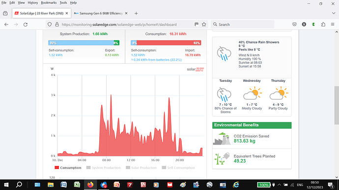
  2. I wish I’d had a larger buffer tank. Mine is just 50l and look at the cycling I get:


    That’s total household power consumption over 24hours, but you can see how dominating the ASHP is (programmed use between 07.00 and 21.00; the two biggest spikes are cooking, so ignore). Samsung told me that once Tw2 hits target temp and switches off, it won’t restart till “about 2degC below this”. How did you go about obtaining software which increases this hysteresis to 5degC?

  3. Just for info, the same Samsung contact (UK Tech Helpline) told me that the maximum ASHP turndown on our model is 50% (rather than the 25% that Ian suggested). So your oversizing (and mine!) may be worse than you thought :thinking:.

Sarah

1 Like

Hi Ian,

On the subject of ASHP oversizing, I fear that in the UK the dice are loaded against new purchasers. MCS rules require installer registration to obtain the BUS grant, and it’s in the installer’s interest to sell us the biggest ASHP they can get away with. Most users could not do heat loss calcs themselves, and even if they can they still have to accept the installer’s sizing (or lose the grant). The MCS rules stink (must be based on having windows wide open even in winter, methinks).

My own prelim sizing (based on every room being good and warm, at the lowest ambient temp we’d ever measured here in Wiltshire) was 3500W, but MCS calcs said 7500W, so I had no option but to accept an 8000W unit.

Now the ASHP is installed, we don’t even heat most rooms (to reduce running costs), so the effective oversizing is even worse.

And it sounds like most purchasers (including Arne) are in the same boat. Time to organise an uprising against MCS?

Sarah

yeah no surprise they won’t commit to anything better than 50% as they publish no spec. I’ve heard 33% from distributors. I’m just going on my practical experience (my 16kw runs stably at 4kw) and data from people on this forum and others. But it could as you say be not as good as 25% in any given system.

your buffer tank - might be worth exploring your setup separately as to why the cycling is happening?

having just done some quick maths Arne’s very oversized system could be smoothed out somewhat by reconfiguring back to a buffered system, but only by using a VERY large buffer. Say you had a 300L buffer to play with: working on temp change of 10C (low 35C high 45C), that requires 3.5 kwh, meaning a run time of 26 min for an 8kw input. Lets say the House takes this out at 1.75kw (for simplicity of maths) .
(edit - maths wrong before, stupid error)
house takes 120 mins to use the 3.5kwh in buffer.
HP recharges it in 26 mins, then does nothing for 94 mins (with suitable controls such that it comes back on only when the buffer drops to 35C)

However it would be at the cost of lower efficiency (HP run temp is always higher than optimal because you have to heat the buffer to 45) and high complexity (would need some clever controls to get the flow temp into the rads right, and wait for the buffer to cool before calling the heat pump, need to change to a higher average buffer temp in cold weather, its becomes a 2 loop system ).

1 Like

Hi Sarah,

Are you sure that not heating parts of your house reduces your running cost?

My heat pump is way too big for my house but I have found it has a minimum electrical input and so there is also a minimum heat output at a respectable or acceptable COP.

Not heating rooms would mean I would use the same amount of electricity and to produce less heat, the heat at the minimum input is free, if you restrict the output by closing radiators you gain nothing.

My approach has been to find somewhere for the heat to go so that I can run at the minimum input for as much of the time as possible.

anti MCS uprising: common thread on every UK based forum where ASHP are discussed!

your system - you should be able to get an 8000W stable down to 2000W in my experience. having rooms turned off may be making it worse not better. worth explaining / exploring your system in detail?

Indeed, by turning off some radiators, the others have to work harder, and heat pump will cycle more. Counterintuitive, but it could be better to heat whole house to one temperature. HeatGeek explains here:

Thanks for the feedback Ian/Matt/Tim.

Point taken about heating other rooms, but:

  1. Our main room has only a single small internal wall (3 external walls) and half the ceiling is also effectively a flat roof, so there’s very limited scope to reduce heat loss by warming other rooms,
  2. The heat loss to the upstairs room (bedroom) keeps it at >10degC in winter with its radiator off, so perfect for sleeping (I wouldn’t want it any warmer).

So I guess I’ll have to accept the need for a higher ASHP flow temp than you (to keep the main room warm), and live with more cycling than ideal. In any case, with a maximum 30kWh/day imported power (below 0degC all day outside, and including cooking) - that’s less than £10/day max in winter - there’s not a huge incentive to invest much more, even on a monitoring system (an extra thermal vest would offer a much better payback… :face_with_diagonal_mouth:).

Sarah

I found that it wasn’t so much about the heat loss to unheated rooms that heatgeek talks about. I found that with the some rooms closed down, I didn’t have enough active emitter area to match the output that my heat pump wanted to throw out, so it would get up to a high circulating temp too quickly and cycle. Simply by having all radiators active, it will stabilise the circulating temp and run for long periods efficiently. and I get warmth in all rooms almost literally for free (or at least for the same input energy).

1 Like

How quickly is “too quickly” Ian? And do you have a buffer tank? Volume?
My system hits target LWT (about 45degC, depending on ambient) 40-50 mins after a cold (~22degC) start, then cycling starts. What do you see on your system?

https://heatpumpmonitor.org/system/view?id=45
https://emoncms.org/app/view?name=WoburnSandsSamsung16kw&readkey=536f3634aa60c0be3d6e00f1c6128e7a

take a look at today from 0300-0400. cold start at 0300. Runs at 2000W input , 6000 to 10000W output, with 3 short off/on cycles. COP of 3.47. This is because all the bedroom radiators are off at this point so there aren’t quite enough emitters in circuit for it to be stable. LWT and/or RWT go over target and it cycles.

compare it to 0600 to 1200. Outside temp is the same. No change to heat pump or circulating pump over the earlier morning run. COP 4.54. the system difference vs earlier is this : all the radiators are on. the gradient of LWT and RWT in the cold start is less, so HP’s control doesn’t see the circuit overheat and feel the need to shut down and cycle. I get one long stable run, output of ~4000w for input of 950W. This is slightly too much heat for the house (by an estimated few hundred watts) so by 1200 the thermostat is satisfied and it goes off. I have a single loop system so the buffer question doesn’t apply.

if you have a buffer: have you balanced the flow rates between the primary and secondary sides? If you have , and the emitters are setup correctly so that they lose heat to the house at the same rate as the heat pump puts heat into the buffer, then its size shouldn’t matter. Its only if the input and output are not balanced would the buffer size come into play . This kind of system its not supposed to be built with a large buffer though. To store heat that comes in at a far higher rate than the house can consume it by using a very large buffer store, is for semi- or un-controlled heat sources like wood burners.

2 Likes

Hi Sarah

I still run similar CoP like I never had before - really strange, but i will wise up during time :slight_smile:

  1. I will look into that if its needed - for now I focus on what is the reason why it produce OK CoP currently

  2. 2011 is at 15/-10 and 202* at 28/46 - The 203* is not in use. I have not spotted it go higher than 40 degC in flow, at any time - Coldest night here have been around -8 approximately.

  3. The company that delivered the unit, is very eager to get it to work smoothly, so they have experienced a lot of trouble with this 1 DegC, as they say is the restart point - so I guess no one really knows, beside Samsung engineers :slight_smile: - But nevertheless, they managed to get this Beta software made by Samsung and it was implemented on my unit 17/11-23. I do not have it - it would also need a S-Net reader/writer - cost about 150 pounds though - this unit can also log every detail out to excel - but thats it I believe. :slight_smile:

  4. When my do its “longruns” - it goes down to 800 watts in the end of a cycle - so around 2800 watt out.
    that is at 3,55 in CoP - I have noticed shortly 400 watts - but we talk below 10 seconds at that usage, so it really does not count…
    Going down to 2000 watt out would be plausible, at CoP around 2,5 - which I have had for a long period.

Guess I will take contact to supplier and suggest them to change it to a 5 Kw or set up a big buffer, like 300 liters - believe its possible to throw in a 300 liter - but the they might need to move the shunt for my floor :slight_smile:

Keep you posted on the progress…

A lot of helpful data there, Ian, even if I don’t fully understand how you’ve managed to draw all those conclusions (I still wear L plates…)

I don’t have a flowmeter on my secondary buffer loop (i.e. radiator flow), but I estimate flow to be about half that of the primary loop (which is metered) based on pump curve and system curve intersection. I can easily increase this (3-speed CH pump, currently on min setting), but can’t picture how increasing rad flow would change things much as LWT and RWT are quite close anyway (5degC dT at startup, even less as LWT target temp is approached). Your dT looks like ~4degC so comparable.

Any comments welcome!

I learned by standing on the shoulders of many giants reading reading and more reading. glyn hudson, john cantor, graham hendra, and particularly marko cosic who sent me countless personal explanations. even with an engineering degree (I have one too!) there is a lot to understand. my system still needs improvement also.

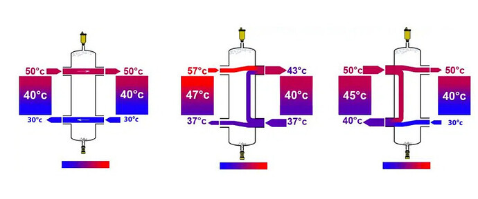
my favourite diagram for buffer/LLH imbalance is this one


which comes from here Low Loss Headers: The Complete Guide For Efficient Design

If you have DT of 5 on the primary and 2x the flow on primary vs secondary then your DT on the secondary will be 10. meaning your MWT in radiators is 2.5C less than it would be if the flow rates and DT’s were the same. meaning your radiator outputs are lower. meaning more likely to get a cycle as the HP overheats the buffer…and/or you have to run with a higher LWT at the heat pump meaning lower COP.

simple golden rule (if buffer has to be there)
Get the flow rates as close to the same as you can. DT the same each side. Primary side a smidgen higher is ok but not 2x.

you want the buffer to be as close to “not there” as you can for your water flows - so that the temps change minimally (as little as possible mixing inside the buffer). like the idealised flow shown in the left hand diagram.

of course no buffer ever has zero mixing, so better, repipe without the buffer, make it into a volumiser, then this issue just goes away.

yes my DT is 4 , I’ve tuned it down from 5, but I have a single loop and a single PWM controlled pump, a different system design to yours.

1 Like