Hi, I’ve seen this asked and answered before but since I’m relatively new to all this and after hours of searching and coming up with nothing I’ll ask…
What are people using to disconnect the battery if a cell goes over/under voltage in the bank? I would prefer a latching relay connected to the diybms relay but can’t find one to handle the current I need that is relatively cheap. (Also I’m not 100% confident in what exactly I need)
Any other options for a 48v battery and 100 amps+. Anyone using something they are happy with that doesn’t cost a fortune?
This is also something I am looking for. Without endorsing any specific company, Shallco makes bistable (latching) relays in 12v and 24v that can handle 200-300 amps, but they are approximately $65 USD each. Add on shipping, and it is close to $100 each. Everything else I have found is at least triple that price.
I’ve looked at SSRs in the past for other projects, but haven’t seen any latching ones that don’t use any power in a energized state, and haven’t seen any in the 100+ amp range either. Don’t MOSFETs use some power in their energized state? You also need to be careful with SSRs, there are a lot of inferior fakes. I bought some “brand name” ones that turned out to be fake, they melted down at 20A despite being rated for 40A!
I’m also curious what other people are using. I can’t imagine most installations just skip a disconnect relay, that seems very risky.
Not cheap but up to 48 volts there are the Victron BatteryProtect units, they go up to 200amps. You can use them as a remote controlled switch or as under voltage disconnecting switch.
I’m working on something that can switch 60 amps at 100 volt. But it seems more difficult as expected. Making it is easy but making it safe is something different.
IGBT’s look interesting. I’ve used MOSFETs and transistors but never used one of these. Someone told me IGBTs are used in electric vehicle drives, low frequency, around 1kHz switching.
This is where the DIYBMS lacks in my opinion. Its cheap until you need to find a solution to this problem. If you only need a single BMS then this is not the product to save on costs. Works out more expensive when I add the circuit breaker with shunt trip than an off the shelf solution.
However I needed a modular type BMS that could continue to change configurations while testing different batteries and pack sizes, so in my case the DIYBMS was much cheaper than buying multiple off the shelf BMS’s for my different configurations.
On Ebay search for Tyco EV200AAANA. The coil is 12 or 24v, draws only 5.5w energized, and is rated for 500 amps. They are very solid units, I’ve used them for years.
I’m still struggling to programm the modules, but I believe, its quite easy to build a latching relay circuit using a cheap high current chinese relay and one or two of the diybms relays. Its just the matter of playing with the rules. Please look at the links. Latching relay circuit schematic
Also modern cars using for disconnecting the battery a relay. The problem with MOSFETS or IGBTs is the voltage drop at the component, around 0,5V. For a current of 200A this is 100W!!
BMSs use mosfets, the more mosfets the great load sharing versus heat they produce, the main price in a lot of BMSs is the mosfets, a rough calc is ohms of the mosfet’s RDS (on) x square of the amps = heat in watts produced
I understand also that MOSFETs have typical On resistance, whereas the IGBT has a voltage drop / current curve.
Nothing wrong with the dissipation of a solid-state device though, just depends on the application. 200A continuous sounds pretty hardcore! Might be absolutely fine to have an IGBT or MOSFET based relay setup, and the losses could be compared over time to the power required to energise a relay.
GAN-FETs look interesting too… I saw a reference to some kind of reverse blocking nature of them? So could act more like a relay without the blocking diode a MOSFET would need. Not sure.
Really? Generally speaking, it is wasted power that has to be got rid of by some means - heatsinks and fans, for example - and paid for. Using @buddhafragt’s numbers, compare the 100 W dissipation with the coil power of a relay - around 10 W (and the latching relay mentioned in post no.3 won’t even cost that power). Solid state switching wins when the rate of switching is such that it is either too fast for mechanical contacts, or contact life will be too short (and those things often go together). Otherwise, relays/contactors have the advantage of minimal voltage drop (less than 150 mV for the Shallco one) and consequently minimal heating.
I did end up buying 2 of the Shallco relays. I was concerned about the dissipation of MOSFETS in a high amperage solution, too. Let’s not forget that all that heat is also wasted energy as well. So I have 1 to use and 1 as a spare part for the future, not that I expect to ever need it. The relay is rated for 100,000 cycles, and everything going well, it should never need to activate.
Now if I could just get some Attinys I’d finally be able to get my BMS up!
Precisely. I’m not sure where the idea that there’s “Nothing wrong with the dissipation” came from - there’s everything wrong with dissipation, it’s losses that carry a cost, often in more ways than one.
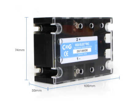
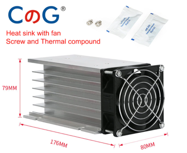
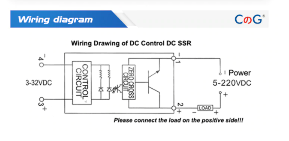
Looking at something like these solid state relays 600DD, rated at 600 amps in 2 versions 220vdc and 600vdc, they look ideals for switching extra large loads, should buy and try them out