I’m curious to know the voltage drop over these devices I tested a few (different type/brand) and was shocked by the high internal resistance and voltage drop.
Those will work, the issue there is that they are either NO (normally open) or NC (normally closed). For safety reasons, you should not use the NC type. That means that you need to use an NO relay and energize the relay at all times to maintain battery power. By the datasheet, that is a constant 12W draw (along with 12W of heat generation).
12 Watts is pretty significant load as you say. How about a servo and a high current switch ? the servo could easily be controlled with an Arduino.
I like the idea of a shunt trip breaker.
My current winter projet I moving from one 16s 100ah pack to 5 separate 16s 50ah modules. Each will have their own diyBMS and I am planning what to add inside the box of each module.
I would like to have hall effect current sensing, a classT fuse for catastrophic protection and then some sort of remote-trip breaker that provides 100A circuit protection, operable by the diyBMS controller. The breaker also serves as the manual disconnect ON-OFF switch.
Question is, what product fits the bill? The usual places (DigiKey, etc) have things but they tend to be rather expensive. Not a big deal on a monolithic battery pack, but it gets expensive when you’re looking at 5 or more of them.
What I need is a battery disconnect relay, like the Intellitec 01-00055-000 (Intellitec 01-00055-000 Relay, 0100055000) but something that can be used for a 48V LFP pack. This device is rated for switching 12V only.
It is essentially a latching or bistable relay. It is closed with +12V on the “I” and 0V on the “S” terminals, and opened by reversing the connections. It requires about 3A impulse to change state, but then doesn’t use any power. I would love to get a version rated to handle 60V / 100A DC.
I’m using a couple cutler hammer shunt trip breakers I picked up on ebay.
They are rated for up to 250vdc (600vac) and come in a bunch of different currents.
If you can’t find the exact breaker you want w/ a shunt trip,
You can pretty easily swap a shunt from one breaker to another,
if they come in the same style of case. (at least that is the case for the 600v cutler hammer units)
For something that isn’t momentary, Chargery makes dc contactors up to 600a / 100v
I just chatted with someone answering the [email protected] email address (Chris Bayus from M&M RV Electronics). The 12V rating is for the coil. And the coil is completely isolated from the contacts. The contacts can handle “any voltage within reason”.
So, for disconnecting my 48V 16s LiFePO4 pack that will have a 200A breaker as a current limiter, as well as a 275V class-T fuse for catastrophic protection, he recommends the 00-00507-712, which is a latching, ignition protected, 12v coil contactor suitable for marine environments. It’s certainly not cheap at about $269 USD. But it provides me with a reference point.
Now, activating the coil requires sending 12V DC in a short pulse to the two coil contacts, “I” and “S”.
+12V to “I” and 0v to “S” to close the contactor
0v to “I” and +12V to “S” to open the contactor.
To provide these reversing contacts, Was thinking of using an H-bridge motor driver capable of sinking about 3-5A for short pulses. I’ve got several in my parts bins due to a DCC model railroad hobby and Arduino RC toy obsession…
Perhaps the ability to support reversing contact relay controls directly in DiyBMS actions could be a useful feature.
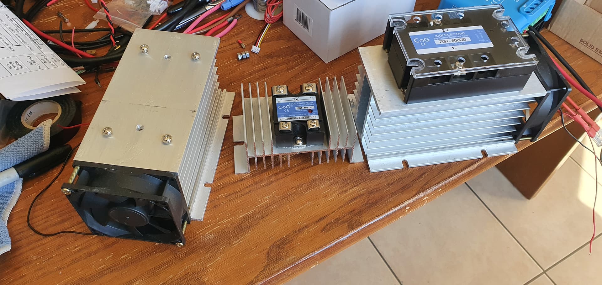
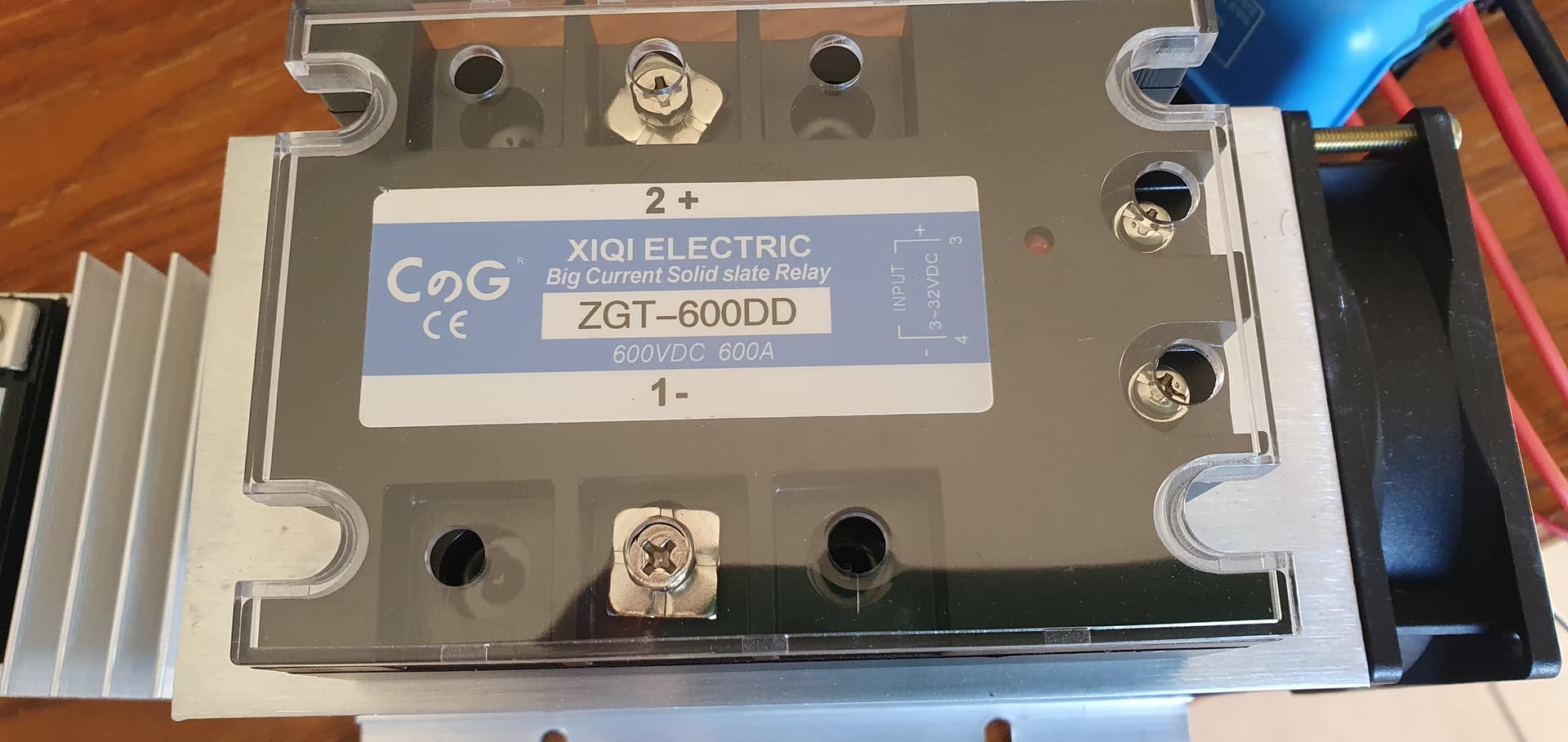
I see them on large cooling blocks even with a fan. I am looking forward for you to share test results as I am afraid they will have a “high” internal resistance and become hot due to the disapated energy.
So has anyone come up with a decent solution for a disconnect? I really do like the Intellitec 01-00055-000 from a couple posts up earlier. I would need to parallel 3 of them to get my 250A that I would need. Maybe I’ll give that a shot. I’d have to see, in mission mode, if I could get the amps to spread evenly… Maybe 4 of them to guarantee that none stay over 100A. What’s nice is they can handle 500A for 30 sec so I wouldn’t have to worry about them having to disconnect exactly at the same time! And $28/each seems pretty good too!
I think that’s the right approach, though I’d be very wary as you have a big variable in the mix – contact resistance. On the big d.c. drives that I used to be involved in some decades ago (8 kA to accelerate), we used multiple cables in parallel and made sure the cable contractor cut each cable to exactly the same length so as to share the current as equally as possible. But the resistances there were predictable - in your case I’d suggest there will be a lot more variation in the contact resistance than we’d ever expect due to cable length.
I think your hope of a guarantee that one will not exceed its rating is, at best, just a hope. If you maintain the contacts in good condition (or if they are sealed, they remain so) and the contact pressure remains correct, you stand a chance.
If you can afford the voltage drop, then you might consider a fixed resistance, in the form of cable, in series with each relay so that the variable contact resistance is a smaller proportion of the overall resistance of that branch of the circuit.
That’s a good point… I couldn’t find anything in the spec sheet for contact resistance. So it may be an order of magnitude higher or lower than the cables connecting it… It also may self correct a little as it heats up it’s resistance will increase too. I guess I would just have to try it and see how balanced it is… I might have to be more concerned about it’s AIC rating… Which is also not mentioned. Can it break 100A+ at 50Vish… It’s meant for 12V… Again I could try it and see if I hear any arcing…
This might be worth experimenting! ![]()
you could try a large stud mounted thyristors – a large 400A one . i am currently building a motor controller board for one - it was for a forklift but I moved the motor in to an old 9n tractor for gardening work around the yard. but the motor controller circuit board died a few years ago hence why I was making one from arduino. basically all the motor controller is two fast thyristors one is +400A and another smaller 50 amp isolated one connected to a large capacitor. to enable i send a single pulse to the large 400a thyristor and it will stay on after that. then to turn off I fire the smaller one which sends a pulse of current to bypass the larger 400 amp one which is enough to trigger the large 400 amp one to shut off. To get the PWM of the motor controller I pulse between the two thyristors – the benefit of the large thyristor is that they do not get hot under very high loads – geez that forklift controller probably has 40 some years on it and the thyristors are still going strong (well built fast russian thyristors that is for sure)
edited __
I was thinking you probably do not need the the second thyristor as what my motor controller does - you could just use a normal ssr. for your main circuit use the 300a thyristor and the for the shutoff bypass, use a ssr that would just need to fire for a moment to create the bypass to stop the thyristor
I’m experimenting with this bistable relay as disconnect
https://www.alibaba.com/product-detail/100A-120A-HIGH-POWER-MAGNETIC-LATCHING_60322942824.html
Sadly despite the claims of 100A continuous current, at 50A I’m seeing temps over 50 degrees!
I see they’re rebadged for sale in Europe. Anyone else tried them?
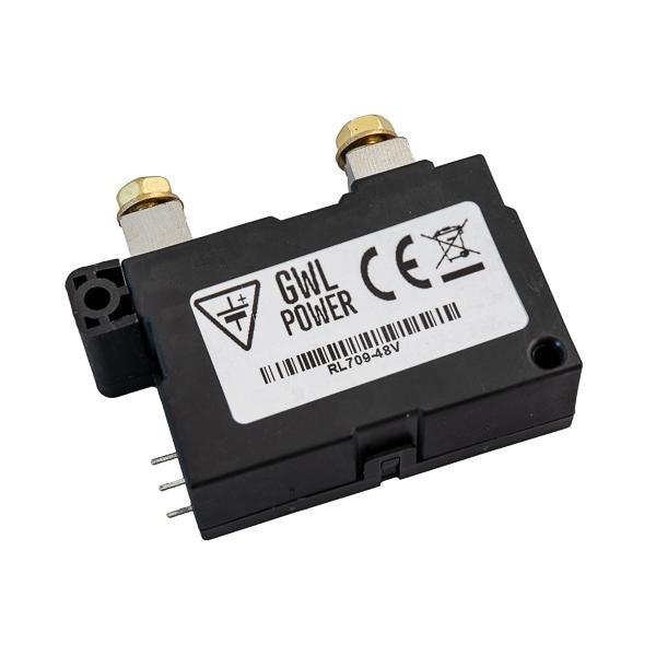
I failed (miserably!) sourcing GWL bi stable relays, and ended up buying a Blue Sea one:
https://www.bluesea.com/products/7702/ML-RBS_Remote_Battery_Switch_with_Manual_Control_-_24V_DC_500A
easy to configure the controller to activate it, not that cheap but tbh not more expensive than the ones mentioned in the thread (just under 300usd)
Haven’t used it in anger yet, bank still in my office waiting for the final shunt chip to arrive.
V.
The bistable relay I have is now so bad it’s >60 degress at 1 amp!
Must be something wrong?
I got the Blue Sea T class fuses and holders locally so should be able to source RBS quickly.
Sadly there doesn’t seem to be 48V version?
I guess I could use a DC/DC converter and use 12 or 24V to fire the RBS for switching 48V.
Something like this should work https://www.aliexpress.com/item/1005003676956737.html?spm=a2g0o.productlist.0.0.448573a9NLlMxQ&algo_pvid=3a271f7d-1be5-42fe-aecd-29fd8397f45e&algo_exp_id=3a271f7d-1be5-42fe-aecd-29fd8397f45e-0&pdp_ext_f=%7B%22sku_id%22%3A%2212000026759848497%22%7D&pdp_pi=-1%3B16.72%3B-1%3B5.06%40salePrice%3BAUD%3Bsearch-mainSearch
Yep, got the relay control confused so the coil was constantly powered.
Much better now.
Andrew,
I would appreciate if you could provide some temperatures when carrying 50A DC constant current if you have labbed it.
I went with the BlueSeas RBS ML-7700 remote battery switch (bistable relay).
The control logic of the version I got is 12v. This works for me since I have a 48V propulsion bank and a 12v house loads bank. other than sharing a common 0v bus and an MPPT charge controller keeping the 12V charged from the 48V, the systems are independent.
The BMS controllers for the 12v and 48v BMSes are powered from the 12V battery. So driving the ML7700 relay is a simple matter of sending the connect or disconnect pulse to their respective relays. Only downside is that the ML-7700 switch takes two relays to operate.
Just to reiterate… the heating issue i was seeing with GWL relay was because of a wiring error on my part that meant the operating coil was permantly powered. It was nothing to do with current handling. I have since tested the relay with >50A and measured no significant temp increase. I would recommend these relays an efficient disconnect device up to the rated 100A.