Looks like I need more help.
Taken the circuit & scope to the meter, and verified that the meter is giving out data at 26Khz on the scope.
The coil picks this up and I’m able to see a very jaggy 26khz sine wave on pin 6 of the opamp.
This is measured at approx 20mv pk-pk.
Knowing this, back on my bench I created an inducted 26Khz signal that generates the approx the same pk to pk voltage at pin 6.
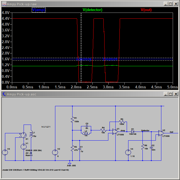
The output then of pin 7 is approx 200mv pk - pk ( looks close to the 6x gain as the signal I could generate varied between 20 & 40mv) with a DC bias of 1.6v
The DC bias output on the other side of the detector diode sits at 1.1V when no input present and 1.3v when there is. The AC portion on the same point (somewhat of a sawtooth) has pk-pk of 200mv
Pin 2 with signal is 1.6v (dc only), pin 3 with signal is 1.3V DC bias with a sawtooth 200mv AC wave.
The output at pin 1 is a steady 600mv DC with or without signal applied - no real AC portion (as expected). Just a flat DC line on the scope.
Therefore, I conclude that the coil is not able to pickup enough signal, or the circuit is not quite right for this application (more gain needed) ?
Any help appreciated… Trying to figure out how to get the traces out of the scope for upload here.
Alan
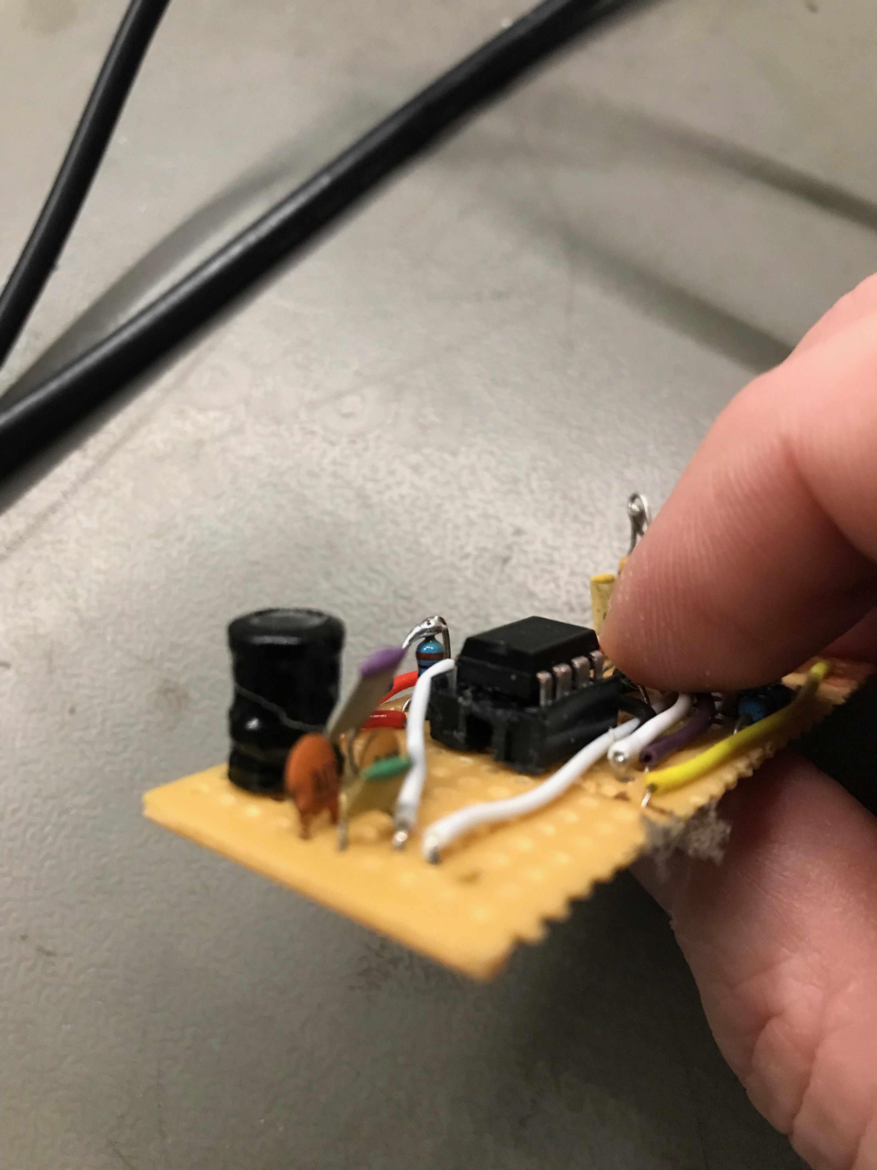
The feedback resistor, R4, I interpreted as 15K from the pic in the original thread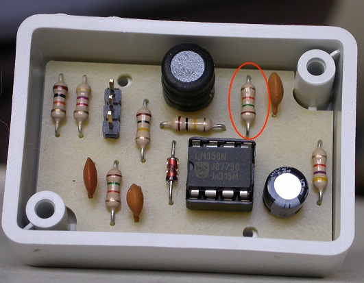 .
.
It’s quite hard from the pic to ascertain if it supposed to 15K or 1.5K (is the band orange or red ?)
If is 1.5, then the gain is 10X more … I wonder is that the issue ?
pic attached with the R4 circled.
In fact doubting values of R2,R5 and R4. It’s really hard to tell if the multiplier band is red or orange.
And it makes a huge difference …
Hoping this is the last hurdle !
I can’t read the pin numbers on your diagram, but pin 6 is an inverting input of the op.amp, and I wouldn’t expect to see any signal there until the output clips, because it should be held to the same voltage as the non-inverting input by feedback action (and that’s a constant d.c. with no signal on it).
Looking at the open-loop gain curve for the LM358, you should be able to get a gain of around 18 × at 26 kHz, so I doubt that R4 is actually 1k5.
The other question - is your coil & capacitor actually tuned to 26 kHz, or do you need to adjust the value of C2?
I think a (another?) problem is d.c. offsets. Ideally, the output of that amplifier op.amp. should sit at a few tenths of a volt above the bias voltage on the non-inverting input, so that the detector diode is just not turned on. Then, in the presence of a signal, the non-inverting input of the comparator op.amp will rise above the inverting input and switch the output to a logic high.
So if you biassed the comparator non-inverting input to 1.2 V, you’d detect the signal.
Looking at all this, can you check the circuit diagram against the pcb again?
The coil is pretty well tuned, as I’ve varied the frequency inducted across it, and it is the amplitude pk-pk output is highest near 26Khz (it’s actually best at 25.5K, but beggars can’t be choosers)
I’ve re-cheked against the PCB, and the only difference is where I swopped pins 2&3 so as to not get an inverted output.
I’m at the bench now with it, so with a fresh pair of eyes going to look and get some more measurements to see what is going on. At the moment, with the 20mv induced signal, the open gain opamp is not switching.
I can’t do much thinking today - I’ve got a bad head cold. I’ll look again in a day or two.
This is the best I can do today. Biasing the comparator to 1.15 V makes it work with just below 200 mV pp out of the amplifier.
I needed to increase my C2, making the ‘on’ state longer.
For a man with a cold, you sure can come up with the answers.
I wasted 6 hrs today trying to debug this, only to find a short on the board which (between pin 1/2) and that drove me crazy. I thought I had changed something and badly broken it.
I follow your thinking and circuit to lower the bias of the comparator. I created a voltage divider and biased it at 1.1v and the circuit is a lot more sensitive. On the bench an inducted current of 40mv pk-pk operates the circuit, whereas before it took well over 140mv…
Now, when I was playing in the rain and dark 2 nights ago outside at the meter, I’m sure I metered the inducted current at 20mV.
But with the changes I may get lucky and hope the circuit is now sensitive enough to pick up the meter.
I will see tomorrow. It’s been a long long day at this…
I simply could not have done this without your help, effort and pointers. The explanation and LTspice analysis really really helps. And it matches closely with what I see on the bench !
Update tomorrow !
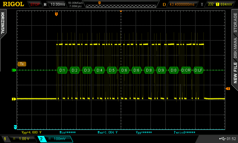
Hmm…
That looks like data to me. Now to decode it. 
I do have some reservations about how reliable the potentiometer approach will be, as it could depend, to at least some extent, on amplifier drift.
A better way would be to generate the bias from a low pass filtered version of the pulse stream. The bias would then sit at the average value of the pulses, and so would more or less ensure that the comparator worked whatever the absolute voltage turned out to be.
However, if the data is absent for a long period, it could easily generate rubbish data from noise.
Yes, indeed it was, and scope decoded it nicely.
It was simply me injecting 1234566890 into the AM stream from a serial port.
So the circuit works on the bench at a low level of input…
Got it.
If this works (which I’ll know shortly), I’ll copy the LPF that is in the original circuit and adjust it for this bias.
I’ve also found that moving the circuit from breadboard to veroboard detuned it slightly (by 2Khz) so small capacitor addition brought it back to 26Khz. I’m hopeful these small kick up the bottoms will allow me to decode now.
Fingers crossed
Well the good news is that picks up something when near the meter.
That’s major progress !
Now I just need to find out what as the programme is not decoding it… (yet)!
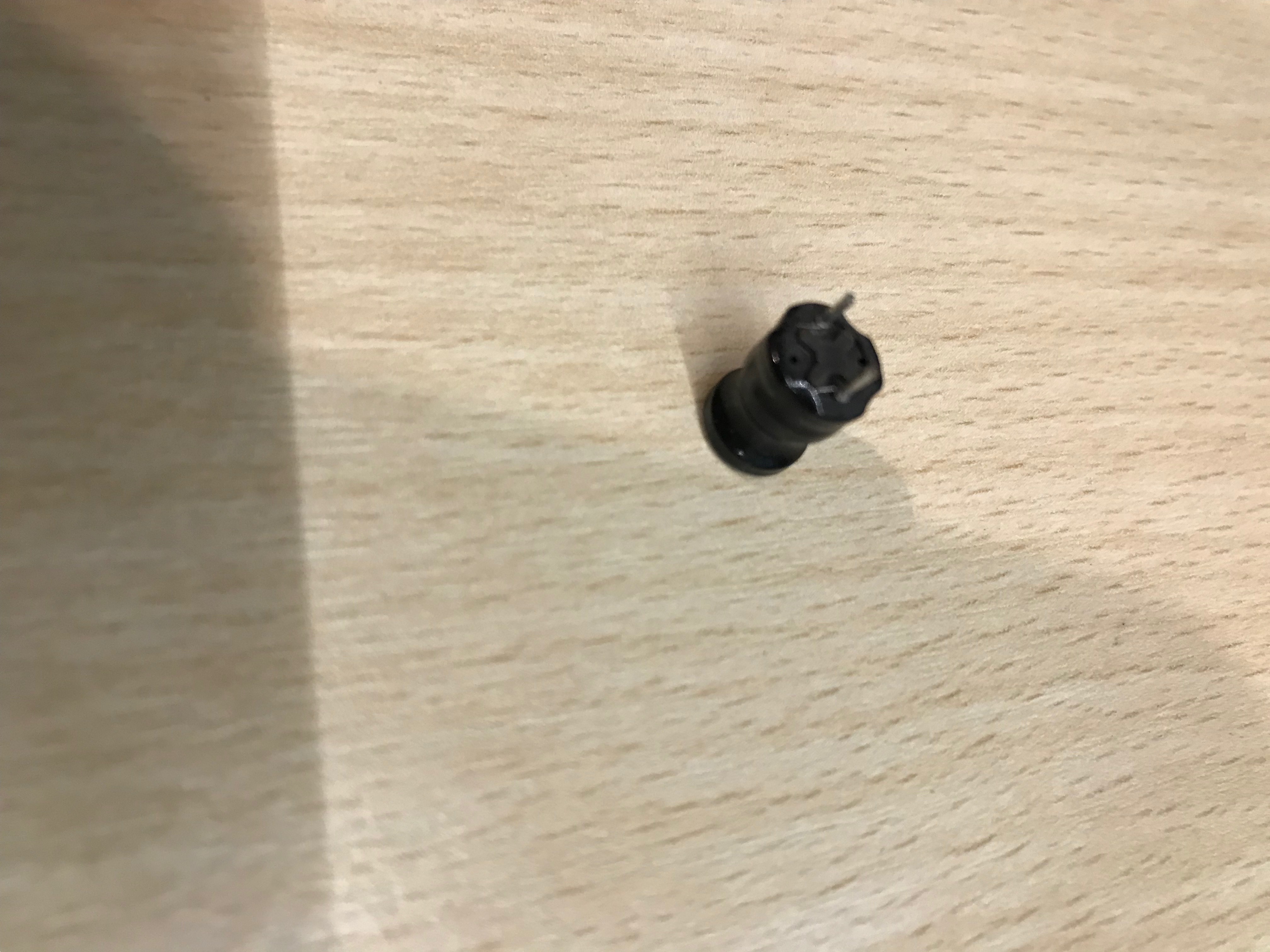
Thinking (a little) laterally, what does your pickup coil look like?
The voltage (given a uniform field out of the meter - unrealistic I know but…) is proportional to the number of turns and the area of the coil. Inductance is proportional to turns2 × diameter × ln(diameter). So for the same inductance, a larger diameter coil with fewer turns should (if the field hasn’t fallen away) generate a larger voltage.
I’ll get a pic over shortly.
All in all another frustrating day.
Looks like the thing was either picking up noise or nothing at all.
Again need to get the scope on to see what is happening which is quite painful working in outside utility cupboard.
There are a couple of 240 wires run right past this meter so I’m sure they aren’t helping. Pics to come.
1 Like
The only thing this looks to pick up is noise.
I can’t get any inductive readings from the meter which makes be the coil isn’t sensitive enough.
Need to think on what you said on that.
But on the bench I can pickup inducted signal via siggen of 0.3v into a 360 ohm resistor. Three wraps of signal wire around the coil though
I’m definitely not an expert on such things, but that pick-up coil just doesn’t look right to me. What do you know about the pick-up coil that you’re using - apart from the inductance? Is it air-cored, or is the core some magnetic material?
What I’m getting at is, was it designed as an inductor or as a search coil? It isn’t shielded, by any chance?
So I know nothing about it at all.
It’s from a bunch of components I bought from a deceased radio ham into building Audio systems.
I didn’t know there was a difference in inductor types. Can you enlighten me further ?
Are there any markings on it apart from the value - maker, part no?
If you’ve put a few turns around the outside and it picks up the current in that, it’s unlikely that it is screened.
The meter and coil are acting a bit like a transformer, that has the primary winding inside the meter, a rather large air gap, and you’re supplying the secondary winding. To get the flux from the primary winding linking with the secondary, obviously the physical alignment must be good, and the coil needs to intercept as much of that flux as possible. I would have expected a larger diameter and flatter coil, that would get closer to the meter, would be better. And obviously the more turns, the better. A ferro-magnetic core - possibly ferrite (of the right grade) could help.
unfortunately not. The value is stamped on the top.
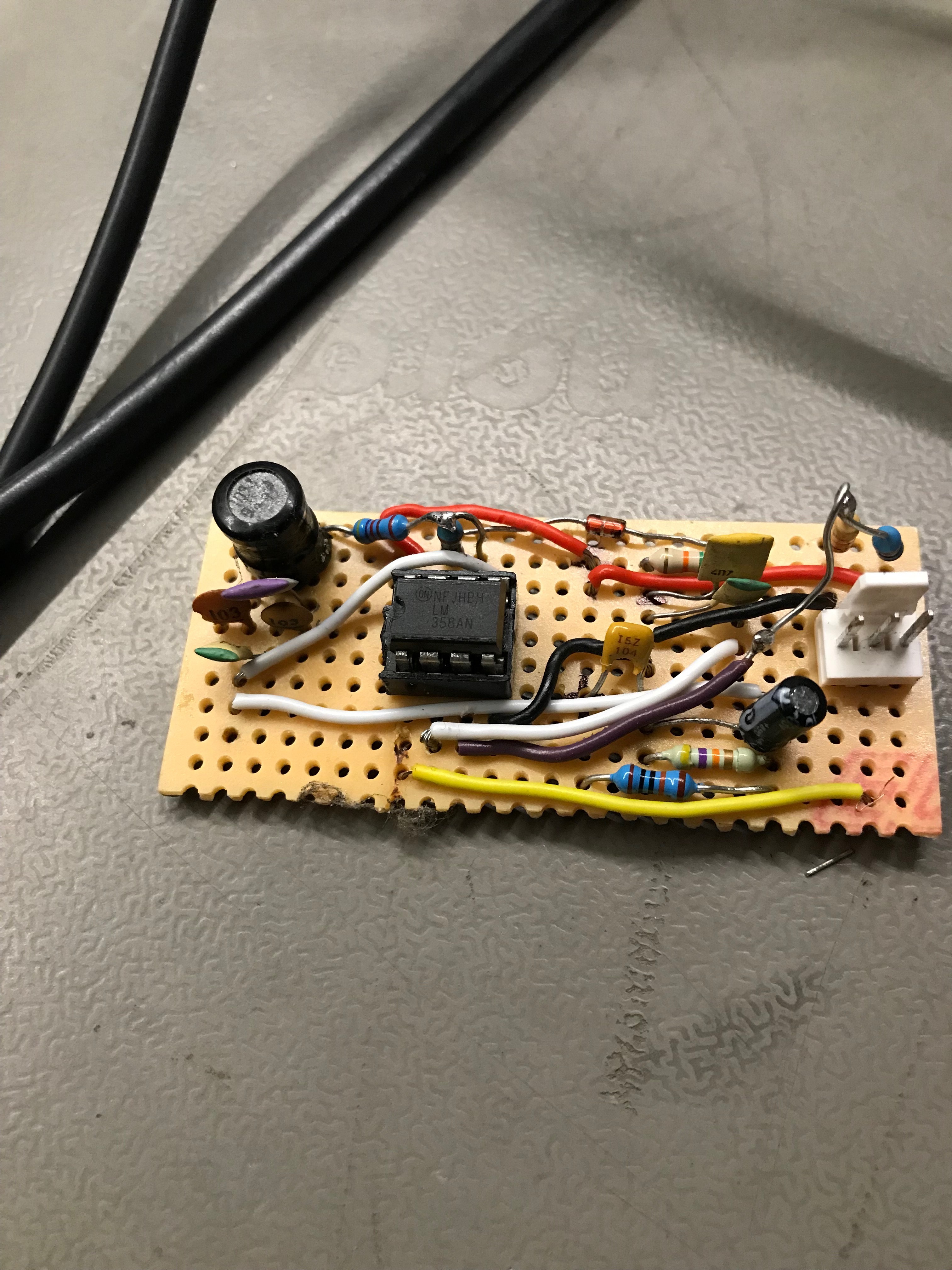
Looking at its construction, it appears not be screened just copper wire covered by pvc type substance.
It looks remarkably like the one in MartinR’s picture.
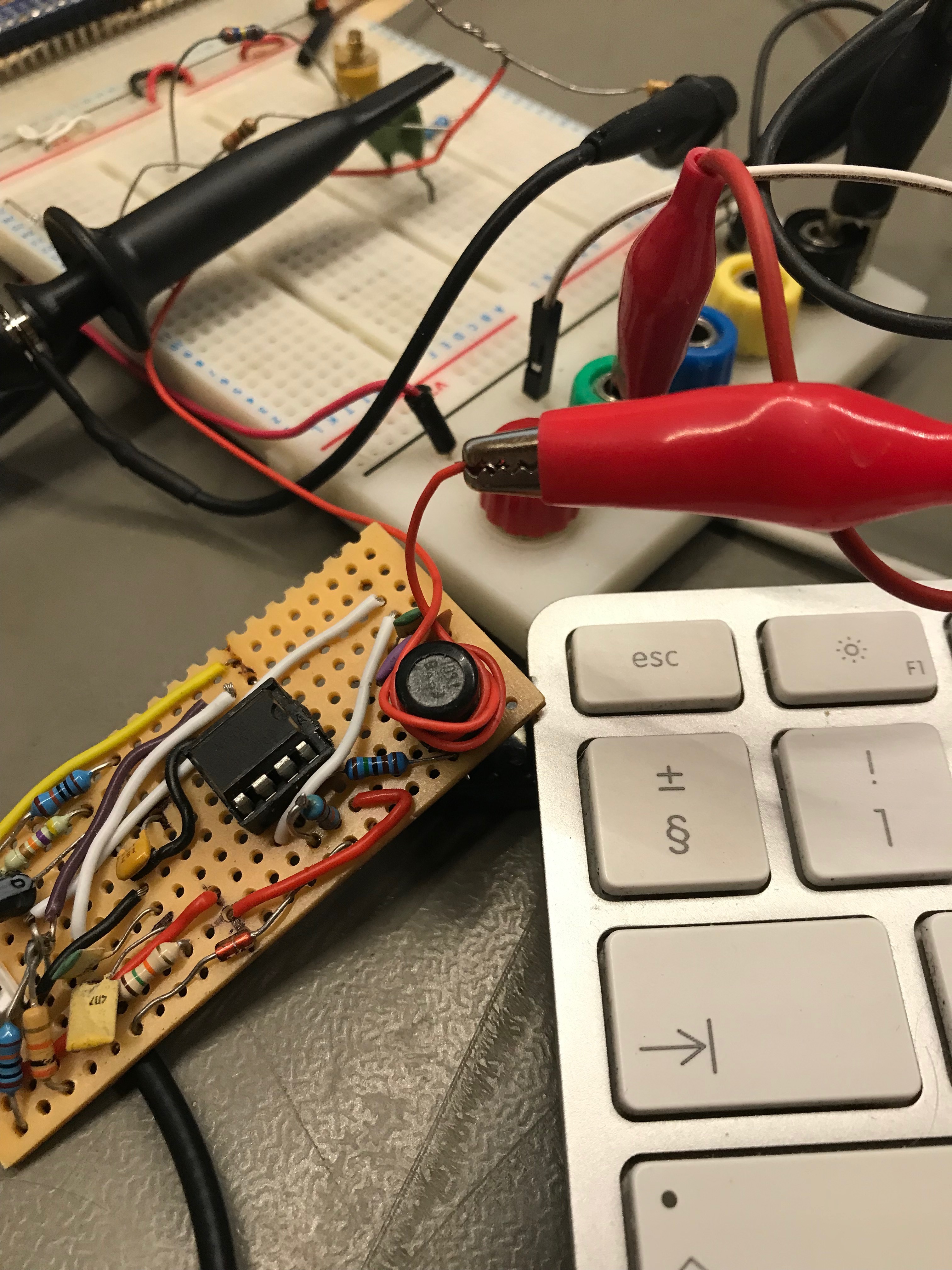
That’s exactly what I’ve done for my bench testing - pic attached.
I’ve got a box of random inductors but most of them look like screened can tuning coils.
In the original thread, “willhey” reported that they found the positioning was critical. Is there an indication on the outside of the meter for the position of the pick-up coil? I presume you’ve checked all around the meter, and in various orientations, looking for a signal? Do we know whether it’s transmitting continuously, or at intervals?
A couple of days ago:
Is that still accurate? Was it really a signal coming out of the meter, or was I right to understand that you thought it was and you’ve now decided that …