You’re in luck ( a little bit, anyway). The sketch came via me. Ampy_meter_reader.zip (1.2 KB)
Unfortunately, the conversion of the ‘active’ Drupal site to the archive had some limitations.
You should be able to reconstruct the circuit diagram from the pictures (for most of the component values) and the PCB layout.
Thank you very much that is useful. Meanwhile I have found where the inductive transmissions come from -
using a bat detector!! - see Reading meters with bat detector - YouTube I figured that the induction might move the ultrasonic microphone a bit - and that proved to be the case. Couldn’t pick up the square wave harmonics on 102 khz though - my scanner wouldn’t go below 100khz - too much general mush.
I think I can work out the circuit from the pictures - unless MartinR , willehey or MattyZee surface that is.
I’ve been trying to reconstruct the circuit, and done a lot of research into how it would work.
However I am really struggling with the value for the electrolytic cap (and it’s function). Is there anyway at all we can get the original attachment from the original forum ? Or can anyone help who may have built a working circuit for inductive reading ?
Sorry. I went back to play some more but the meter had been changed. Apparently we had changed supplier and, unusually, they changed the meter as well. Good luck.
Um, my best circuit drawing style.
I think I’m good with the values of the LC portion, the power rail filter cap, and the high pass filter (bottom left?)
The electrolytic : i cannot understand it’s purpose… but it is in the input chain of both opamps…
The one at the “top” of the image, in parallel with the 47 …Ω to GND? That with the two resistors - 100 kΩ and 47…Ω is doing exactly the same job as the 10 μF and the 470 kΩ resistors in the emonTx input - providing a smooth, ripple-free, low impedance bias for the op.amps*, so that the output can swing either side of a voltage somewhere between the two rails. If we guess the frequency is super-audio (say above 10 kHz) and that 'bottom’resistor is 47 kΩ, then 1 uF should be more than adequate, with a voltage rating greater than the supply voltage but not by more than necessary. (The reactance of that at 10 kHz is 16 Ω - low enough I think.)
* In the emonTx, it’s to hold the input at midrange of the ADC, not of an op.amp.
How it works
It’s actually a fairly conventional amplifier - detector circuit. Starting with the coil, that must have enough area and enough turns to pick up as much signal as possible from the meter. It is tuned to resonance - or close to - by the parallel capacitor. If you can’t exactly match the coil construction, that capacitor will need to change to suit the coil’s inductance. f = 1 ÷ (2π√(LC)).
The coil’s voltage is amplified by the first op.amp (pins 5, 6 & 7) with a gain of 100/15, and the output of that goes to the a.m. detector (the diode, the 15 kΩ and 1 nF). Out of that will come the envelope of the signal out of the meter. I’m guessing that will be pulses carrying the data. That is further amplified and squared up by the second half of the op.amp (pins 1, 2 & 3), which is working at open-loop gain (i.e. very high).
The two critical parts there are the coil and its parallel capacitor, which must be tuned to the transmitted frequency, and the capacitor in the detector circuit, which must be large enough to smooth out the carrier frequency (the coil frequency) but small enough to not smooth out the data pulses.
Robert, Thank you so much for your explanation and help !
I didn’t see this message until now (not sure why I didn’t get the alert) and have spent the past 2 days learning about how all of this works. The principle of operation you have explained really well to me, so thank you for taking the time to do that. It is now much clearer what should be happening.
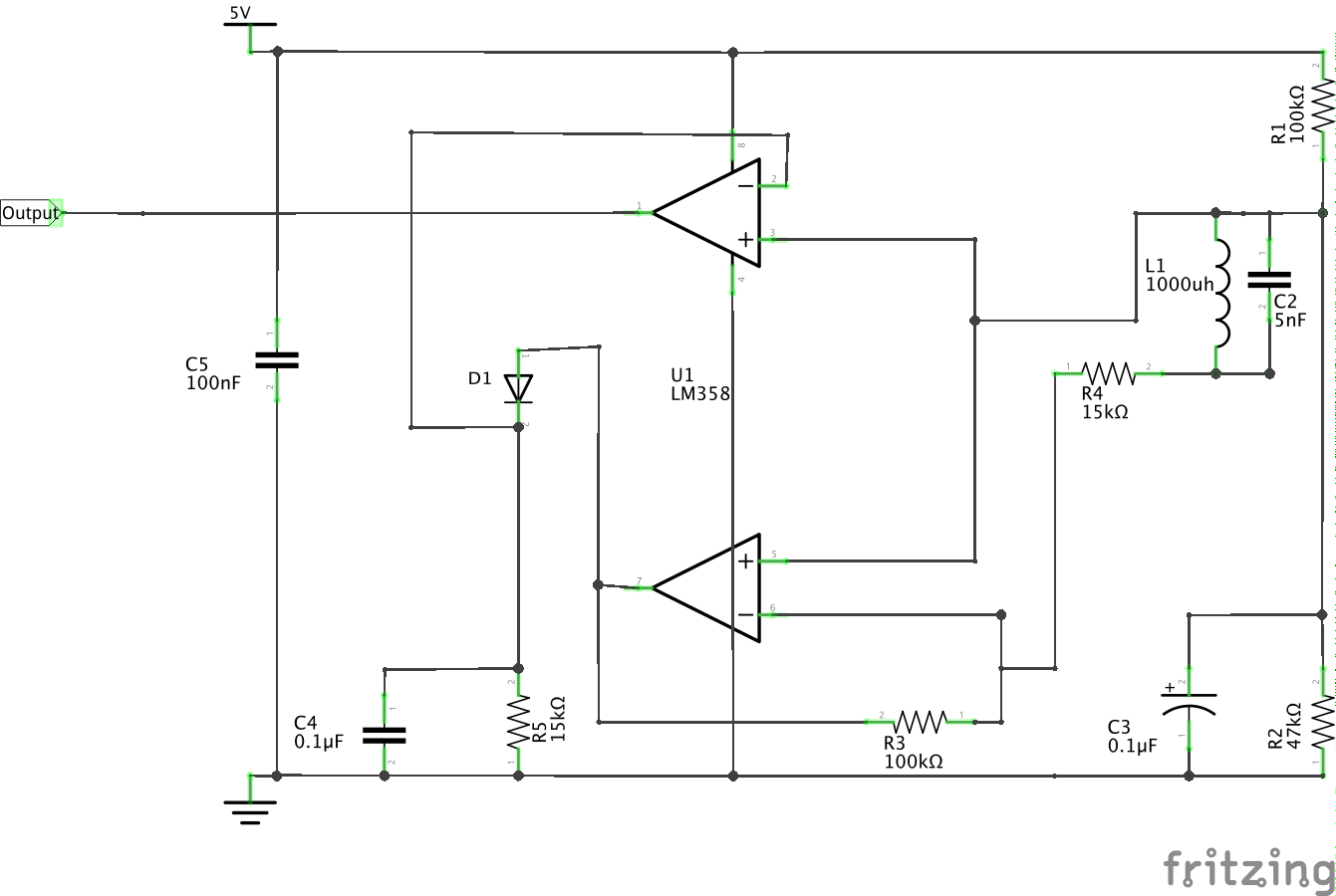
Sorry the image is so badly drawn, attached is one done with Fritzing (awesome programme!)
I’ve got the coil & cap calculated and oscillating nicely at 26Khz (1000uh & 5nf).
With experimentation and some calculations (which may well be wrong), I’ve went for 0.1uf for caps C3 (electrolytic) & C4 (detector) - do you think they are valid ? C4 in particular - the frequency is 26Khz carrier and I 2400 baud (say 3Khz for margin of error). If not, I’ll go for your recommendations !
Thanks again for responding, this little project has really stuck in my claw and I’m determined to get it working… if nothing else it may help others and save me a trip to read the meter !
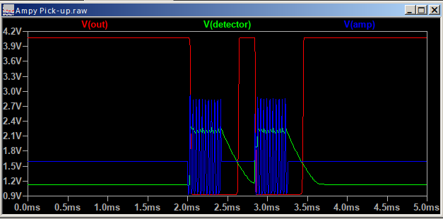
This is with a 0.3 V amplitude signal from the pick-up coil (simulated with a signal generator and modulated by a switch).
It shouldn’t be oscillating, it should be resonant, if that’s the frequency that the meter sends out. If it’s oscillating on its own, you won’t be able to detect the signals from the meter.
If it is oscillating on its own, you might need a large electrolytic in parallel with C5 - 22 μF, or a damping resistor in parallel with the coil.
BTW, it’s normal, when drawing a circuit diagram of this sort of thing, for the signal to go left to right.
Yes, 2400 baud, according to the manual.
Can you share the equation on calculating c4 ?
I tried quite a few, and used 1/(2pi * RC) as the formula for the RC values, solving for C using a cut off frequency (fo) as 6634. The cut off frequency was chosen with information gleaned here
I calculated fo using the formula :
fc = carrier freq
fd= data freq
fo=√ (fc * fd)
fo = √ (26000 * 3000)
fo = 279
Then solving for C4 , I arrive at 38nF (not sure how I got 0.1uf last time, it was 3am I guess !)
Now, finally my new signal generator arrived today, (was using an arduino to drive 26khz!) so I can experiment and see what it does.
One final question, the signal is DC biased over 2v or so, how exactly does D1 rectify in this case , as the signal will always be higher than the turn on voltage (even the negative of the ac waveform does not go below 0.7v)
Thanks again for helping a newbie with this stuff !
As I said, the time constant must be long in relation to the carrier frequency, but short in relation to the bit length of the modulating signal. I’m fairly sure an amateur radio textbook will tell you, but if you want to know how I did it, I guessed a number based on the bit length and checked it in LTSpice.
This is what 38 nF looks like:
That’s not giving a very clean pulse train.
It’s just pumping the voltage up a bit, enough for the comparator op.amp to switch. It’s not very sensitive, it needs about 0.2 V amplitude (0.14 V rms) to work.
Happy to report it’s all working on my bench.
The £43 I spent on the sig generator was well worth it. It allows me to create an ASK (digital AM) signal using an external input to modulate. Using an arduino, I wrote a small program to write at 2400 baud to the serial port. Using this as input to sig gen and putting the output of the sig gen into a small wire wrapped around the coil and onto a small load resistor, after some fiddling it all works beautifully !
I sure learnt a lot following the signal through the circuit.
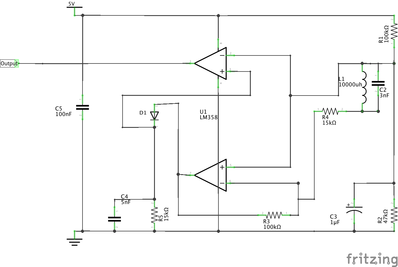
I did find an error in the circuit, in the original circuit as I uploaded, the output was inverted. Swopping pin 2&3 (2nd stage opamp) corrected that.
Again, thanks for all your help, I could not have got this done without your explanation and helping my calculations which were, ahem, dodgy to say the least.
Correct circuit attached (and next time I will draw from left to right
I’ll post when I get this off the breadboard and stuck onto the meter to see if it all really does work
Maybe not an error, you could have changed that in the software that decodes the message, quite simply by calling a high voltage input a logic ‘low’, and vice versa.
Or maybe, the software already does that (I haven’t looked), in which case you can either swap the op.amp back to as it was, or “unswap” it in the software.
So the software uses Software Serial and doesn’t invert any bits. That said, maybe the meter output is inverted itself. I’m going to recheck the PCB layout and see.
I just tried the circuit on the side of the meter, but alas no output was seen by the arduino (inverted or otherwise).
Next step is to take a scope down to the meter (which is outside and it’s raining hard !) and see what I can see. really curious if any signal is being picked up at all…
My first guess will be you need to adjust the tuning capacitor across the coil. The second is, if the coil Q is too high, it will still be ringing (and the detector detecting) during the signal breaks. The cure for that will be a damping resistor in parallel with the coil - start high ( a few kΩ) and reduce until you get a clean digital output. @Bill.Thomson is the expert in this area.
I hope after all this that you do have a meter that does radiate a signal.
So on the ‘does the meter have the inductive output’ - that crossed my mind.
According to the manual for this model, it seems to do so, it does not appear to be optional. Manual
On the bench, with a 26Khz modulated signal, the pulses are clean, and the HF noise isn’t there. There doesn’t appear to be ringing or anything else abnormal with what I see on the scope.
To test on the bench, a 5V square wave modulated signal loaded into a 360K resistor and 3 wraps around the coil was able to be detected and processed perfectly.
I wonder is the signal from the meter not strong enough, or … well who knows. Hopefully the 'scope will tell me tomorrow what (if anything) is going on.