PV router - linky problem

Here are my last adjustments and the power record of this day Power measure 28-04.zip (359.4 KB)
Do you have about the same regulation? I hope 3043 will increase accuracy.
And Ok I reach reading % with:

lcd.print(100-percent);
  1. //###### Adjustable settings #######

  2. int upperRANGE = 80; // the range in which it will not search for better output

  3. int lowerRANGE = -80;

  4. int PWM =1 ; //1=enables PWM.h smother output 0=disable

  5. int FRAC =4 ; // fraction of grid Hertz ie 50hz-> 2=1/2 (25hz pwm) 4 =1/4 (12.5 hz pwm)

  6. const int CT1 = 1; // divert sensor - Set to 0 to disable if using optional diaplay ( wind)

  7. const int CT2 = 1; // Inverter sensor - Set to 0 to disable

  8. const int CT3 = 1; //grid sensor

  9. const int CT4 = 0; // windgen sensor - Set to 0 to disable disable if using diverter display

  10. int LCD = 1; // 1=enable 0=disable

  11. float element = 30000; //wattage of element for diversion - make bigger then then what you have to decrease buuble search sensitivity

  12. int SSR4 =1; // 1= 4 ssr and disables static, 0= 3 SSR & 1 static ( disable PWM.h)

  13. int ios = 1; /// Number of SSR to control 4 MAX if PWM.h diasble otherwise 3

  14. int pulse = 11; // pin for pulse disable if you cascade on 4 ssr pin 11 does not work if PWM.h enabled

  15. int pulse1 = 9; // pin to use to divert on 1 SSR

  16. int pulse2 = 10;

  17. int pulse3 = 3;

  18. int pulse4 = 11; //enable pulse 4 if you wish 4 cassacding ssr

  19. float DRIFT =1 ; // if you wish to adust hz output

  20. int invstatus = 5; // pin for led display showing overproduction

  21. int type = 0; // 0= casdading - 1 = equal for diverting

  22. int ssr=0; // 0= zerocrossing 1 = phase angle currently only supports one ssr

  23. int AVG=5;

when i look at your grid where it jumps around +/- 40 and when there a rapid change there a a spike this way and that way

here a sample from a stable solar output – there are little spike on and off as devices come on and go off
solar_and_grid.csv (34.0 KB)

but i have the same high and low spike as it only adjust the output after it sees it so that is expected

But I think you should reduce the 80 … but if you find it works the best at 80 at that for you - no worries…

But also have to remember you are dialing down a substantially sized element when it comes to accuracy… but looking at your image it seams you are using mostly of the steps already as it firing at 15% the moc3041 I used originally only started firing around 20 - 30%… if you want better accuracy put in an element that is 1/2 the size ie 1500w then the SSR will run at 50%… as 3000/750 watts( your peak power) you can only use 25% of your usable steps at best… – curious does your tank have 2 elements ? top and bottom elements – if you run them in series that reduces their output by 4 … and that would match your panel perfectly

I have measure the resistance voltage for different load
It seams ok…


Hey david would you mind trying this version
i made a software library for firing the triac and SSR… you should be able to use it with hardware zerocossing hardware or the emulated hardware zero crossing ( it much more accurate with hardware though)… but seams to work fine with software emulation. nicest part you can use it across all digital the PWM pins with the same results

FRAC I have set at 4 it seams to work the best for 60 hz… but since you have an scope you can adjust it better. set FRAC to 1 and your FREQ just sample analog A0 and the pulse then adjust BL an OL to fall close as you can to zero crossing …

let me know if you get this one to work better for you on the 50hz grid there not so much “ping” on this version on 60hz

oops accidentally uploaded the wrong one yesterday – if you downloaded it could you download it again

Hello Stephen,
Don’t forget that my english is quite limited… I am sorry not to be able to understand all from your last message :sweat_smile:
I have tried to load your last program … but I do not reach to make it working, it is very unstable when begining to load the SSR. (just by looking the LED of activation connected on Pin 9)
I do not understand the using of BL & OL maybe with a quick drawing you can indicate influences of each?
Is it easy to add from emonlib the daily energy counter (kWh) from PV & diverted
Thank you

hi there I borrowed code from another library and made it work with software zerocrossing ’

here a reference … material
latching is the delay faced by electronic devices (zero cross detector, switching unit) to respond. If you face latching problems in your circuit, use the setLatch() function to absorb them. You will need an oscilloscope with two channels in order to see what’s going on. Connect channel1 of the oscilloscope to the AC mains, and the other one to the pwm pin of the Arduino board.

(a) Observe the delay between the zero crossing point and the fall of PWM pulse from ON to OFF state. If the falling of the PWM pulse is before the zero crossing point of the AC mains, set the basicLatch parameter to a positive value, in MICROSECONDS. If the falling of the PWM pulse comes after the zero crossing point of the AC mains, set the basicLatch parameter to a negative value, in MICROSECONDS. Obviously, if the two points coincide, set the onLatch parameter to zero. Load the script and test. Readjust if necessary.

(b) Set the duty cycle to 50%. Observe the PWM pulse on the oscilloscope and calculate the difference d = onPeriod - offPeriod. Set the onLatch parameter to onLatch = d, in MICROSECONDS (may be negative as well).

hope that more understandable :slight_smile:

energy counter
do you want to do it right in the sketch ? if so I would go around doing it this way- set up another counter for each feed you want… grid solar and divert

use a round robin database to store and trim your data such as this one set it to grab data from grid info every hour and tell it to average out over your time period you want displayed … you will need to modify the library

edit rrd .ccp to handle your data here 

int RRD::read() {
  if (analog) {
    return analogRead(pin);
  } else {
    return digitalRead(pin);   // just remove digitalRead so it captures your  data instead
  }
then  use this
grid24avg = gridRRD.average(); to display the info 

define GRIDtime 3600000 // every hr
int cntgrid =0;
int griddata =0;
int gridinfo;
int grid24avg;

void setup{
RRD gridRRD(“rrd”, gridinfo, 3600000, 24);
gridRRD.start();
}
then in void loop
in the grid CT at the beginning put
cntgrid++;

then after
grid = emontx.power3;
griddata = griddata + grid;
boolean alotted = false
if (!alotted && millis() > GRIDtime) alotted = true;

if (alotted)
{
gridinfo = gridData/cntgrid ; // this give you average of the last hour
gridData = 0;
cntgrid = 0;
grid24avg = gridRRD.average();
}

here just insert this into the appropriate spots in the code .the RRD suggested above does not trim the RRD it just start a new one at every cycle. this one does first it collects input for 1hr then averages it over the hr to give you Wh then it adds it to RRD. so you can display Wh and the Wh over a 24 period ( just divide by 1000 if you want kWh)… remember this only keeps track from it last reboot

// EmonLibrary examples openenergymonitor.org, Licence GNU GPL V3
#define FILTERSETTLETIME 5000 //  Time (ms) to allow the filters to settle before sending data  

#include "EmonLib.h"             // Include Emon Library
EnergyMonitor emon1;             // Create an instance

int cntRRD=0;
int VAL1[] = { 0,0,0,0,0,0,0,0,0,0,0,0,0,0,0,0,0,0,0,0,0,0,0,0 };
int VAL2[] = { 0,0,0,0,0,0,0,0,0,0,0,0,0,0,0,0,0,0,0,0,0,0,0,0 };
int VAL3[] = { 0,0,0,0,0,0,0,0,0,0,0,0,0,0,0,0,0,0,0,0,0,0,0,0 };
int EnergyData1 =0;
int EnergyData2 =0;
int EnergyData3 =0;

static const unsigned long RRD_INTERVAL = 1000; // sample period for 1 hr set to 3600000
boolean settled = false;

void RRD( int _RRD, int _ARRAY)
{
  if (_ARRAY == 1){ EnergyData1= EnergyData1 +_RRD;}
  if (_ARRAY == 2){ EnergyData2= EnergyData2 +_RRD;} 
  if (_ARRAY == 3){ EnergyData3= EnergyData3 +_RRD;}

  static unsigned long lastRefreshTime = 0;
  
  if(millis() - lastRefreshTime >= RRD_INTERVAL)
  {
    lastRefreshTime += RRD_INTERVAL;
  //###############  shifts data ine array value #############
                int Data1 =0;
                int Data2=0;
                int Data3=0;
                
 for (int r=0;r<23;r++){
  int Old = 23-r;
  Data1 = Data1+VAL1[Old];
  int New = 22-r;
  VAL1[Old]=VAL1[New];
 }

 for (int r=0;r<23;r++){
  int Old = 23-r;
  Data2 = Data2+VAL2[Old];
  int New = 22-r;
  VAL2[Old]=VAL2[New];
 }

 for (int r=0;r<23;r++){
  int Old = 23-r;
  Data3 = Data3+VAL3[Old];
  int New = 22-r;
  VAL3[Old]=VAL3[New];
 }

 EnergyData1=EnergyData1/cntRRD;
 Serial.print("1 period ");Serial.println(EnergyData1);
 VAL1[0]=EnergyData1;
 Serial.print("24 period ");Serial.println((Data1+EnergyData1));
 EnergyData1=0;

 EnergyData2=EnergyData2/cntRRD;
 Serial.print("1 period ");Serial.println(EnergyData2);
 VAL2[0]=EnergyData2;
 Serial.print("24 period ");Serial.println((Data2+EnergyData2));
 EnergyData2=0;

  EnergyData3=EnergyData3/cntRRD;
 Serial.print("1 period ");Serial.println(EnergyData3);
 VAL3[0]=EnergyData3;
 Serial.print("24 period ");Serial.println((Data3+EnergyData3));
 EnergyData3=0;
 
 cntRRD=0;
  }
}
void setup()
{  
  Serial.begin(115200);
  
  emon1.voltage(0, 146.46, 1.7);  // Voltage: input pin, calibration, phase_shift
  emon1.current(3, 60.606);       // Current: input pin, calibration.
}

void loop()
{
  cntRRD++;
  emon1.calcVI(20,2000);         // Calculate all. No.of half wavelengths (crossings), time-out
  
  int grid       = emon1.realPower;  //extract Real Power into variable
  Serial.println(grid);
 

  // because millis() returns to zero after 50 days ! 
  if (!settled && millis() > FILTERSETTLETIME) settled = true;
  //// ##### if you wish to send data  
  if (settled)                                                            
  {     
 RRD(grid, 1);
 RRD(2, 2);  // inverter
 RRD(4, 3);   // diverter                                                                                                    
  }

}

My Scope is only one channel (PCscope) so will not be able to perform your test.
I change the MOC3041 to MOC3043 and and I do not observe any difference even at low load.
Thank you for the code I will try to integrate it this WE

@David_Joncour
It might be possible for you to make those measurements if your oscilloscope has an “External trigger” input (déclencheur externe). Trigger the oscilloscope using the mains voltage, connect the probe also to the mains and notice where the zero crossing point is.
Move the oscilloscope probe to the PWM pin and then you should see the time difference relative to the mains voltage. Do not alter the trigger settings!

brought out my wifi-oscilloscope have not used it since my hard drive died. took a bit to remember how to set it up :smiley: 
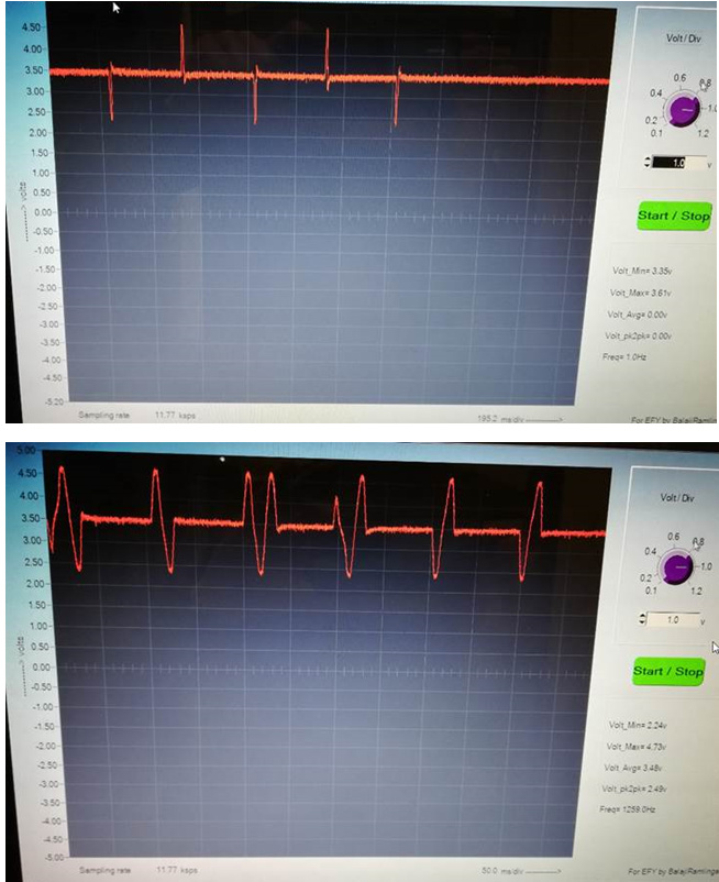
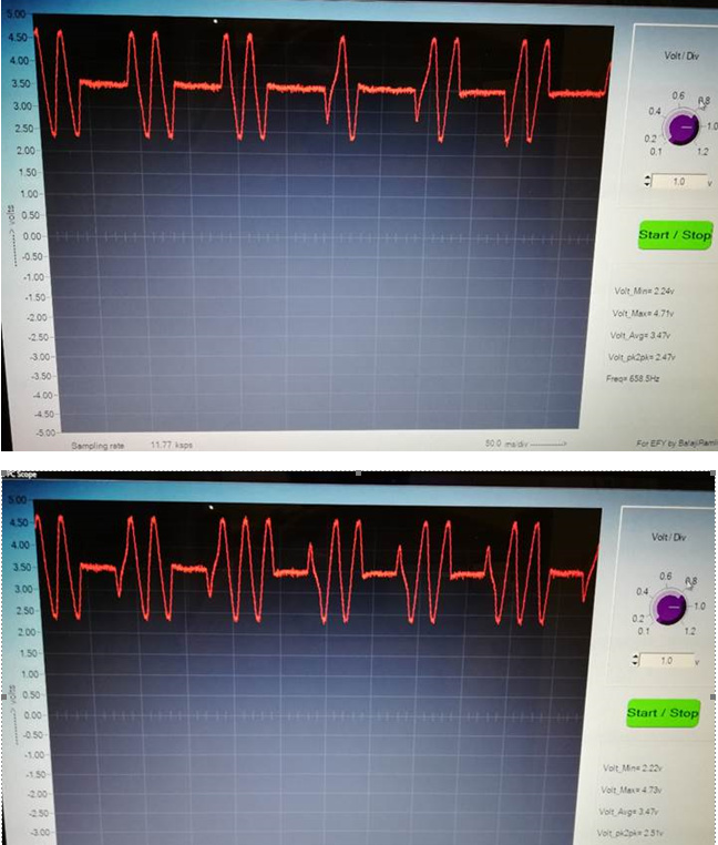
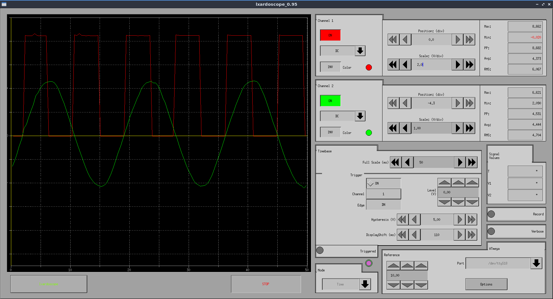
. but it seams to me my ACpwm2 library is working well… with a little fine tuning … here a snapshot…

hits it mostly on the zero crossing which is not too bad considering it only a software emulation

update: okay I think I see why ACPWM it does not always preform to it best if you having it running with one CT. it runs well great… but as the more ct you add it the worse it preforms… it looks like it have to be a sandwich in the middle my MCP3008 daughter board… as with that the sampling was several times faster if I remember correctly… and try to trim my code to work as fast as possible …

curious @Robert.Wall is the newer emonlib code faster??? then the the older version or about the same

emonLib has not changed for quite a long time. When I last checked it - and there have been no changes that I know of since - the speeds with a standard emonTx are:
  calcIrms( ) - approx 5588 current samples per second.
  calcVI( ) - approx 2535 pairs of voltage & current samples per second.
This was published with a few more details and hints at Sampling rate of emonLib

emonLibCM is totally different, because while it samples each input much faster, it handles all the channels as a sample set (for 4 current channels reading V I1 I2 I3 I4) continuously; rather than V I1 for 200 ms, then V I2 for 200 ms, etc. Therefore, when reading 1+4 channels, the actual sample rate for emonibCM is about 1900 sample sets per second, against 2535 for just one current channel with emonLibDS (Discrete Samples). Everything about emonLibCM is in the documentation that comes bundled with the library in the download zip file.

hi david one last one if you want to try. I added in “magic number” I used it for years it does not require zero crossing detection. the only thing is I do not know if it works on 50hz grids but it is the frequency of 13. I have used it for fan speed control, heating element control — but I could never figure out how to get frequency of 13 before on uno I could only do it on an esp.

you use pwm.h

int magic = 13; // magic number-- 60hz = 13, 26, 52 
boolean magicNumber = true;  // enable disable magic number
boolean WEMOS = true; // if you are using a wemos for ondemand adjustment via network connection

if you are using wemos r3 uno/wifi you can adjust on demand

if no wemos just set WEMOS to false and put a static number in magic…
perhaps 13 works there perhaps not

13/60 = .21666 perhaps 50hz magic number is 11, 22 and 44

magicnumber.zip (7.2 KB)
on a 1000 watt element - at 50% load
13 , 26 and 52 hz stay generally within +/- 10 watts range … the only thing certain frequency work better at higher and lower ranges or motor control versus heating element

Hello Stephen, I am working to install the two chanels oscilloscope, first install ubuntu (yes I come from far) and then begin to understand how all this is working. I clearely begin to be out of my confort zone with you… thank you
And I have draw my arduino connection on Fritsing it can be more clear to explain my connection.


I will also trying to play with your magic number

1 Like