Pulse monitoring of Solar but LED stays on overnight

Hi folks, I have been using emoncms to monitor house, PV and Powervault battery usage with two emonTX and CT clamps, but recently decided to (finally) add a Pulse sensor on the PV meter, to verify the solar generation, and improve the accuracy of PV monitoring.

Yesterday I connected the Pulse sensor to the Elster A100C generation meter and into the RJ45 port on the emonTX V3. Initially it looked good, the green LED on the Pulse sensor flashed, and the emonhub log showed the pulse data and CT clamp data being received on my RPi 3 with local emoncms.

I did discover some issues which need further investigation, but just after 8pm as the sunlight faded, my local emoncms stopped receiving any data from my emonTX, not just for the pulse count but from the CT clamps. It looked like the emonTX had failed.

Checking the emonhub log I could see it was still receiving valid RF data, but all of the fields were 0, except for P1 which was counting down from 10 to 1 with each successive packet. I recognised this as being the ‘start-up’ sequence for the emonTX, and effectively the emonTX was in a constant reboot loop.The red LED on the emonTX that flashes when RF data is transmitted was on permanently.

I disconnected the Pulse cable from the RJ45 port and the emonTX immediately started working again, uploading data from the CT clamps.

I think the smoking gun here is that when the sunlight drops, my Fronius PV inverter goes into a low power ‘sleep’ mode, and when this happens, the LED on the Elster generation meter is lit permanently. It appears to me that this condition is not expected by the sketch handling data from the pulse sensor, and causes the emonTX to keep rebooting?

The emonTX is running emonTXCm_v2.0 sketch.

Does anyone have any suggestions?

Many Thanks. Ian

Which emonTx V3, V3.2 or V3.4? – because I can’t identify a sketch called “emonTXCm_v2.0”

I am reasonably sure I tested emonLibCM for exactly that problem and as far as I remember, not only did it not exhibit the behaviour you describe, it also counted the extended “pulse” only once, whereas previous algorithms (IIRC) counted a pulse each time it reported.

I do wonder whether there’s a fault on the optical detector or a power supply problem that’s causing the emonTx to reboot?

Meanwhile, I shall check an emonTx V3.4 using the demo sketch published in the emonLibCM Version 2.2.2 (15/9/2022) zip file.

Further


I don’t have a spare optical pulse detector, but I know from tests I carried out many years ago that the output is a logic ‘high’ (3.3 or 5 V) when the sensor is illuminated and the LED is lit. I am only able to test with a mechanical switch using the internal pull-up in the pulse input, and this presents a permanent 3.3 V to the pulse input (confirmed with a multimeter) and the switch pulls the input to GND when closed.

I have checked and the above sketch and library perform exactly as required: the sketch runs with a permanent logic ‘high’ on the pulse input and does not count pulses; when the switch is closed, it counts one pulse even if the switch remains closed for an extended period, and does not count another pulse when the switch is released.

The effect of the pull-up on the input should exactly emulate (as far as the logic is concerned) the permanently lit sensor, so I am unable to replicate your fault.

You might wish to note that emonLibCM allows you to specify the switch debounce period, which should be zero for the optical pulse detector, and the edge on which to trigger, rising ( 0 → 3.3 V) or falling (3.3 V → 0). The default is

  EmonLibCM_setPulseMinPeriod(20, (byte)FALLING);          // 20 ms 

There is more about the circuitry inside the optical pulse sensor here, including measurements: First try with EmonPi - Pulsecount stuck at 1; some is repeated here: Monitoring energy via utility meter pulse output — OpenEnergyMonitor 0.0.1 documentation

Hi Robert, thank for your reply. The emonTX is difficult to access, but I will have to get to it to confirm which model and I will have to get a UART connection to confirm the sketch installed (the sketch name above was from the config I had captured when I used avrdude to install the sketch into the emonTX in March 2021. My notes show I got the code from Releases · openenergymonitor/EmonTxV3CM · GitHub and based on the dates, I expect it would have been v2.1.0, but I will attempt to confirm that.

Regards. Ian

From that, you probably have emonLibCM v2.0.4, which has the pulse counting algorithm that counted “stuck” pulses such as you get when the meter LED stays on, and has been superseded. I’m not prepared to say this will cause the sketch to restart, but I can try to check for you. If it does, then changing to the latest emonLibCM (V2.2.2) should cure your problem. If it doesn’t, then I don’t know, but I’d suspect a power supply dip is causing the restart.

Hi robert, that’s encouraging, and so I will update the sketch this weekend - many thanks for your prompt response.
Ian

I’m just trying to set up ‘your’ sketch and emonLibCM


The good news (for me) is the sketch and the version of emonLibCM I think you have doesn’t cause the emonTx to restart, but the switch debounce leaves a lot to be desired (not that this affects you because the optical sensor doesn’t have mechanical contacts that bounce).

So the bad news for you is, I think you’re looking at a hardware fault - either the pulse sensor itself is drawing too much current and pulling the power supply down, or the power supply is so weak that it can’t support the pulse sensor (which I find very hard to believe, but worth checking if you can), or it’s the plug or cable.

Looking at the circuit of the pulse sensor, it’s fed from the 3.3 V. We don’t know what the photo-diode is, but let’s guess a couple of mA maximum when it sees the led and saturates Q2, which will sink around 6 mA. Q3 will add about 0.3 mA, so probably under 8-10 mA, which agrees closely enough with the Shop page’s (almost certainly measured) 7.5 mA.

A simulation shows this current should not materially affect operation if you are using the a.c. adapter as both the voltage reference and the power supply.

Hi Robert, the hardware is only labelled “emonTx v3”. It was ordered in 2015. I can provide a picture if that would help?

I was able to get a serial connection, and was able to capture the start up when the pulse sensor was not connected:

22:27:33.316 -> OpenEnergyMonitor.org
22:27:33.316 -> No EEPROM config
22:27:33.316 -> Settings:
22:27:33.316 -> Group 210, Node 15, Band 433 MHz
22:27:33.316 -> 
22:27:33.316 -> Calibration:
22:27:33.316 -> vCal = 268.97
22:27:33.316 -> assumedV = 240.00
22:27:33.316 -> i1Cal = 90.90
22:27:33.316 -> i1Lead = 4.20
22:27:33.316 -> i2Cal = 90.90
22:27:33.316 -> i2Lead = 4.20
22:27:33.316 -> i3Cal = 90.90
22:27:33.316 -> i3Lead = 4.20
22:27:33.316 -> i4Cal = 16.67
22:27:33.316 -> i4Lead = 6.00
22:27:33.316 -> datalog = 9.96
22:27:33.316 -> pulses = 1
22:27:33.316 -> pulse period = 100
22:27:33.316 -> temp_enable = 1
22:27:33.316 -> Temperature Sensors found = 0 of 1
22:27:33.316 -> Temperature measurement is NOT enabled.
22:27:33.316 -> 
22:27:33.316 -> RF whitened
22:27:33.316 -> RFM69CW only Node: 15 Freq: 433MHz Group: 210
22:27:33.316 ->  
22:27:33.316 -> POST.....wait 10s
22:27:33.316 -> '+++' then [Enter] for config mode
22:27:44.608 -> CT1 detected, i1Cal:90.90
22:27:44.608 -> CT2 detected, i2Cal:90.90
22:27:44.608 -> CT3 detected, i3Cal:90.90
22:27:54.805 -> AC missing 
22:27:54.901 -> MSG:1,Vrms:3.22,P1:272,P2:521,P3:499,E1:1,E2:0,E3:0,pulse:0
22:28:04.813 -> MSG:2,Vrms:0.18,P1:81,P2:452,P3:425,E1:3,E2:0,E3:0,pulse:0
22:28:14.809 -> MSG:3,Vrms:0.18,P1:81,P2:455,P3:428,E1:4,E2:0,E3:0,pulse:0
22:28:24.766 -> MSG:4,Vrms:0.17,P1:81,P2:451,P3:425,E1:5,E2:0,E3:0,pulse:0
22:28:34.687 -> MSG:5,Vrms:0.16,P1:80,P2:449,P3:423,E1:6,E2:0,E3:0,pulse:0
22:28:44.697 -> MSG:6,Vrms:0.18,P1:81,P2:451,P3:425,E1:7,E2:0,E3:0,pulse:0

As you can see the AC adaptor was not conencted at this point, as my vague memory was that I could only get a serial connection to work when the emonTx was powered only from the UART connection.
I then connected the pulse sensor to the emonTx but the serial connections only recorded the following:

22:28:53.046 -> emonTx V3.4 EmonLibCM Continuous Monitoring V2.00
22:28:53.046 -> OpenEnergyMonitor.org
22:28:53.046 -> No EEPROM config
22:28:53.046 -> Settings:
22:28:53.046 -> Group 210, Node 15, Band 433 MHz
22:28:53.046 -> 
22:28:53.046 -> Calibration:
22:28:53.046 -> vCal = 268.97
22:28:53.046 -> assumedV = 240.00
22:28:53.046 -> i1Cal = 90.90
22:28:53.046 -> i1Lead = 4.20
22:28:53.046 -> i2Cal = 90.90
22:28:53.046 -> i2Lead = 4.20
22:28:53.046 -> i3Cal = 90.90
22:28:53.046 -> i3Lead = 4.20
22:28:53.046 -> i4Cal = 16.67
22:28:53.046 -> i4Lead = 6.00
22:28:53.046 -> datalog = 9.96
22:28:53.046 -> pulses = 1
22:28:53.046 -> pulse period = 100
22:28:53.046 -> temp_enable = 1
22:28:53.046 -> Temperature Sensors found = 0 of 1
22:28:53.046 -> Temperature measurement is NOT enabled.
22:28:53.046 -> 
22:28:53.046 -> RF whitened
22:28:53.046 -> RFM69CW only Node: 15 Freq: 433MHz Group: 210
22:28:53.046 ->  
22:28:53.046 -> POST.....wait 10s
22:28:53.046 -> '+++' then [Enter] for config mode

And nothing else appeared on the serial connection. However the emonTX was transmitting RF packets recording it’s boot up, which appeared in the emonhub log. Although this time the countdown only got to about 7 and then restarted from 10 each time.

I tried turning teh AC adaptor back on, but it didn’t seem to make any difference - nothing on the serial connection, and RF messages showing it was rebooting. As soon as I dosconnected the RJ45 pulse cable, the emonTx rebooted and started transmitting working data for the CT clamps.

The AC charger for the emonTx was also ordered from the OpenEnergyMonitor shop back in 2015.

I’ll try uploading to the newer sketch next. Thanks for your help and support .

Ian.
Unfortunately it won’t. The emonTx V3.4 appeared in January 2015, so it is probably a V3.4.

I don’t think that will help. It’s got all the hallmarks of not enough power to supply the pulse sensor and itself. What is its normal power source? What’s the temperature where it’s installed?

I’ve never had that problem, and I can’t see how it could be a problem. That’s weird.
The 5V on the USB, UART, RJ45 and screw connectors is all the same wire/track. The 3.3 V for the processor and radio is derived from this with a MCP1702 voltage regulator.
The a.c. adapter feeds via a diode, current limiting resistor and a smoothing capacitor a MCP1754 3.3 V regulator which, via a link, also feeds the 3.3 V rail.

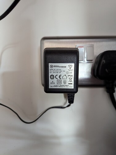
The emonTx is powered from the AC adaptor supplied from the OEM shop back in 2015. The label shows:
Ideal Power. Model Number: DB-06-09.
PRI.: 230-240VAC 50Hz 10VA
SEC.: 9VAC Max 6VA

I do have 3 CT clamps connected, one of which I can remove as it’s a bit of a duplicate. I’ll do that and see if it makes any difference.
Regards. Ian

I very much doubt if you’ll be able to see or measure any difference. All that will happen, if you unplug the c.t., is it will skip calculating the numbers for that channel and report a zero instead.

You have not mentioned any temperature sensors - are there any?

The smoothing capacitor that turns the half-wave rectified a.c. from the a.c. adapter into smooth-ish d.c. for the regulator might have dried out and no longer doing as it should if it’s been kept very warm for its 8-years life, this is one of my lines of thinking.

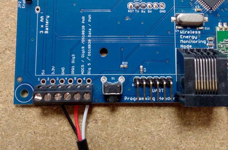
Your programmer should be feeding it 5 V, with enough current to support the pulse detector as well as everything else. Do you have a meter you can use to measure the 3.3 V power rail (it’s available on the screw terminals)

Screw terminals

If that voltage moves (downwards) when you plug in the pulse sensor, then that is the problem. But the cause? Unless you have a resistor that you can dab across the 3.3 V supply to simulate the pulse sensor, I can’t think of a way to determine whether it’s the emonTx failing because it can’t supply enough current, or the pulse sensor is drawing too much current and causing it to fail. (You’d need 470 Ω - that will draw 7 mA and not quite as much load as the sensor, or 390 Ω - 8.5 mA and a little more load than the sensor.)

Apologies I forgot to answer that question - the emonTX and the PSU are installed in the kitchen. Not close to any heating devices, but obviously indoors. I don’t have a temperature sensor on this emonTX (I do have one on the newer emonTx in the garage).

I do have a meter, and whilst I would call myself an amateur in using it, this is an opportunity to learn! Likewise, I bought a collection of transistors and resistors a couple of years ago, so I’ll see if I have anything close to the 470 ohm.

1 Like

The reason for asking about temperature sensors is those too draw a significant current.