First try with EmonPi - Pulsecount stuck at 1

Hi,

I have just setup a new emonPi which I assembled myself (as in connected the emonpi board to a RPi3 I already owned). At the moment I have only connected one sensor - the pulsecounter. The pulsecounter is flashing away merrily but within emoncms the value just seems to be stuck at 1.

Where do I need to start looking to understand why it isn’t counting up?

grep pulsecount /var/log/emonhub/emonhub.log
2018-05-08 21:36:50,297 DEBUG MQTT Publishing: emon/emonpi/pulsecount 1
2018-05-08 21:36:55,279 DEBUG MQTT Publishing: emon/emonpi/pulsecount 1
2018-05-08 21:37:00,243 DEBUG MQTT Publishing: emon/emonpi/pulsecount 1
2018-05-08 21:37:05,422 DEBUG MQTT Publishing: emon/emonpi/pulsecount 1

Thanks,
Barney

Are you accumulating the pulses on the Inputs page, before sending the accumulated total to the Feed?

This is what my inputs page looks like:

The pulse count should be accumulated in the Atmega front end, do you/can you get any other data from the front end, i.e., have you followed the schematic when you connected the serial data lines?
A very silly question: you are in the correct RJ45 socket?

What else is in the emonhub log - particularly from Node 5?

Silly questions are usually the best! I have checked and it is in the right RJ45.

Here’s a bit more logfile:

2018-05-09 05:17:06,403 DEBUG    RFM2Pi     6162 NEW FRAME : OK 5 0 0 0 0 0 0 0 0 0 0 0 0 0 0 0 0 0 0 0 0 1 0 0 0 (-0)
2018-05-09 05:17:06,406 DEBUG    RFM2Pi     6162 Timestamp : 1525843026.4
2018-05-09 05:17:06,406 DEBUG    RFM2Pi     6162 From Node : 5
2018-05-09 05:17:06,407 DEBUG    RFM2Pi     6162    Values : [0, 0, 0, 0, 0, 0, 0, 0, 0, 0, 1]
2018-05-09 05:17:06,407 DEBUG    RFM2Pi     6162 Sent to channel(start)' : ToEmonCMS
2018-05-09 05:17:06,408 DEBUG    RFM2Pi     6162 Sent to channel(end)' : ToEmonCMS
2018-05-09 05:17:06,591 DEBUG    MQTT       Publishing: emon/emonpi/power1 0
2018-05-09 05:17:06,593 DEBUG    MQTT       Publishing: emon/emonpi/power2 0
2018-05-09 05:17:06,594 DEBUG    MQTT       Publishing: emon/emonpi/power1pluspower2 0
2018-05-09 05:17:06,596 DEBUG    MQTT       Publishing: emon/emonpi/vrms 0
2018-05-09 05:17:06,597 DEBUG    MQTT       Publishing: emon/emonpi/t1 0
2018-05-09 05:17:06,598 DEBUG    MQTT       Publishing: emon/emonpi/t2 0
2018-05-09 05:17:06,600 DEBUG    MQTT       Publishing: emon/emonpi/t3 0
2018-05-09 05:17:06,601 DEBUG    MQTT       Publishing: emon/emonpi/t4 0
2018-05-09 05:17:06,602 DEBUG    MQTT       Publishing: emon/emonpi/t5 0
2018-05-09 05:17:06,603 DEBUG    MQTT       Publishing: emon/emonpi/t6 0
2018-05-09 05:17:06,604 DEBUG    MQTT       Publishing: emon/emonpi/pulsecount 1
2018-05-09 05:17:06,606 INFO     MQTT       Publishing: emonhub/rx/5/values 0,0,0,0,0,0,0,0,0,0,1
2018-05-09 05:17:08,031 DEBUG    RFM2Pi     Discarding RX frame 'unreliable content'? 12 7 145 57 90 47 112 155 48 209 146 232 242 255 66 133 226 160 45 27 232 (-93)
2018-05-09 05:17:08,663 DEBUG    RFM2Pi     Discarding RX frame 'unreliable content'? 17 0 130 190 223 167 65 137 241 182 13 62 86 74 66 160 65 35 29 227 5 (-100)
2018-05-09 05:17:10,199 DEBUG    RFM2Pi     Discarding RX frame 'unreliable content'? 0 38 240 216 1 224 6 138 23 8 151 236 214 27 89 241 27 243 62 180 0 (-101)
2018-05-09 05:17:11,447 DEBUG    RFM2Pi     6163 NEW FRAME : OK 5 0 0 0 0 0 0 0 0 0 0 0 0 0 0 0 0 0 0 0 0 1 0 0 0 (-0)
2018-05-09 05:17:11,450 DEBUG    RFM2Pi     6163 Timestamp : 1525843031.45
2018-05-09 05:17:11,450 DEBUG    RFM2Pi     6163 From Node : 5
2018-05-09 05:17:11,451 DEBUG    RFM2Pi     6163    Values : [0, 0, 0, 0, 0, 0, 0, 0, 0, 0, 1]
2018-05-09 05:17:11,451 DEBUG    RFM2Pi     6163 Sent to channel(start)' : ToEmonCMS
2018-05-09 05:17:11,452 DEBUG    RFM2Pi     6163 Sent to channel(end)' : ToEmonCMS
2018-05-09 05:17:11,570 DEBUG    MQTT       Publishing: emon/emonpi/power1 0
2018-05-09 05:17:11,573 DEBUG    MQTT       Publishing: emon/emonpi/power2 0
2018-05-09 05:17:11,574 DEBUG    MQTT       Publishing: emon/emonpi/power1pluspower2 0
2018-05-09 05:17:11,576 DEBUG    MQTT       Publishing: emon/emonpi/vrms 0
2018-05-09 05:17:11,578 DEBUG    MQTT       Publishing: emon/emonpi/t1 0
2018-05-09 05:17:11,579 DEBUG    MQTT       Publishing: emon/emonpi/t2 0
2018-05-09 05:17:11,581 DEBUG    MQTT       Publishing: emon/emonpi/t3 0
2018-05-09 05:17:11,583 DEBUG    MQTT       Publishing: emon/emonpi/t4 0
2018-05-09 05:17:11,585 DEBUG    MQTT       Publishing: emon/emonpi/t5 0
2018-05-09 05:17:11,587 DEBUG    MQTT       Publishing: emon/emonpi/t6 0
2018-05-09 05:17:11,588 DEBUG    MQTT       Publishing: emon/emonpi/pulsecount 1
2018-05-09 05:17:11,590 INFO     MQTT       Publishing: emonhub/rx/5/values 0,0,0,0,0,0,0,0,0,0,1

The emonhub.log confirms the pulsecount is not increasing in the emonpi firmware, ie the pulses are not being counted, therefore the count cannot increase in emoncms.

Is it very bright where you have the sensor? It needs to see a substantial change in light level to work, distinguishing a bright led in bright ambient light or a dim led in low ambient light may be difficult and/or erroneous.

Is the LED on the sensor flashing? Although not a definitive test, it is usually a good indication of whether a pulse is being detected. But you could try moving it very slightly to see if it has an impact.

You could test it with a different light source eg in a bright environment just putting your finger over the end and removing it momentarily to get a pulse or using a flash light, phone screen etc should register a pulse.

Check the RJ45 plug is fitted securely, you should be able to see if any of the gold contacts are not fully home or sometimes if a single wire is adrift inside you can see that through the clear plastic (but not always).

Thanks Paul,
It’s in an outbuilding which was dark overnight. The green LED on the back of the pulse counter is flashing in sync with the meter. I have tried re-seating the the RJ45 but will have a closer look at the wiring. I’ll also try a temperature sensor to try and work out if its the Board or the sensor.

Is there anything special to attaching the pi and the emonpi board? Could I have done something wrong here?

I think an error here would prevent the emonpi board working at all and we can see it is working in the emonhub.log.

As I say above, that isn’t a definitive test, you should/could still try moving it slightly. But a better test is to use your finger (to cover) and a light source (eg torch).

The pulse sensor uses a pulse input pin (rj45 pin 6) where as the temp sensors use a 1-wire bus (rj45 pin 4) so that test isn’t definitive either, especially as the optical sensor LED is working so power is assumed to be good and the temp sensor can work in “parasite mode” which means it doesn’t actually even need a vcc, just data (pin4) and ground.

I understand what you’re getting at, but the one I tested here put the output to a clear ‘high’ well before there was enough light to get the green LED on, so it’s a fair assumption that there is a pulse on the output wire.

Can @bardal see a pulse on the RJ45 socket, pins 5-6?

and I understand what you’re saying, but “a pulse” requires a level change to be detected and from what you say, it is possible to turn the LED on and off (by varying the light level) without dropping below the “logical high threshold” to register a pulse.

As I have said before, I have been able, to order, get either an led flash with no pulse detected or a pulse detected with no led flash dependent on position alone, this was running at 3.3v using a Pi and the same pulsing LED.

Indeed, it does depend on a decent level of darkness. And you’re absolutely right, with careful control of the light level, the output will remain at a voltage where the input will not go ‘low’ even though the LED is firmly out.

Hopefully, as I mentioned elsewhere, I’ll be able to come up with some numbers. Without that, it’s largely guesswork.

I do think though, that this device has come from a design where some assumptions have been made, and not all of which might be valid in all conditions. It does seem surprising that there would appear to be no means of adjustment for a threshold level.

What’s the best way of testing for a pulse on pins 5-6? Is that plug pins or some pins on one of the boards? I have an ammeter but no scope.

Also, is there a wiring diagram showing how the pulse counter should be wired to the RJ45 plug? I have a stray wire on one side of the plug which doesn’t look right to me.

There’s precious little information available about the pulse sensor, almost everything we know is in this thread, or on the shop page. You can use a voltmeter across pins 5 & 6 on the RJ45 socket - I see 3.28 V looking out of the window, 0.7 V in darkness on an emonTx (3.292 V supply).

The plug on mine is moulded on, with no stray wires, so a photo might help. Can you see how many wires actually go to contacts on the plug, and which pins?

Some measurements:

I used a white LED reading lamp, with several layers of draughting film over the front to attenuate the light. The sensor was therefore looking at a bright but diffuse patch of light approx. 30 mm in diameter.

EmonTx V3.4

Condition Output voltage Distance to light source
Just detecting logic '1' 1.42 V 570 mm
LED just visible 3.28 V 460 mm
LED bright 3.28 V 400 mm

EmonPi

Condition Output voltage Distance to light source
Just detecting logic '1' 1.35 V 710 mm
LED just visible 4.05 V 540 mm
LED bright 4.05 V 450 mm

Observations:

  1. The sensor appears to be sensitive to a wide spectrum of colours, even well into the blue.
  2. It was also very sensitive to light on the edge - i.e. entering between the pair of sticky pads, which seemed totally ineffective at blocking light from the side.
  3. When reading the table, bear in mind the inverse square law.
  4. A Weston light meter read ‘3’ at 570 mm from the light source (~ 35 lux).
  5. It would appear that when used with the emonPi, the output is being clamped by the protection diodes in the Atmega 328P’s digital input circuit. As we don’t know what the output circuit of the sensor is like, this is not good. (@glyn.hudson please note.)

@pb66
It seems quite possible that there can be enough ambient light to hold the output at a logic ‘1’ even though the green LED has gone out; in which case of course no pulses will be detected.
If @bardal sees pulses overnight, that would seem to confirm this is what’s happening.

[Edit - 20 June 2020]
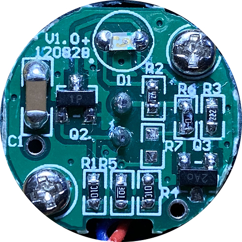
This is the circuit board of the sensor:


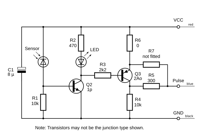
And from that the circuit diagram:

Cct Dgm

Thanks to @warrenashcroft for providing the photo, and confirming the circuit details.

2 Likes

It’s hard to make out but it looks like the plug has wires into pins 2, 5 and 6.

Indeed, I had to use a hand lens looking on the end of the connector.

Which is as it should be.

So assuming the sensor itself is working, it leaves the possibility either of a fault in your “emon” Atmega328P board, or (as Paul suggests) is it possible that there’s enough ambient light to prevent the pulse input going to a logic low? If your meter is in darkness overnight, the green LED is out and it’s still stuck at 1, the latter seems unlikely.

You can prove whether the board is counting pulses: Unplug the sensor and short pins 5 & 6. If the pulse count moves (it may well jump by quite a few counts), the board is counting.

A slightly more refined test: Do you have a multimeter capable of measuring 5 V d.c. and some fine test prods? If so, you can prove whether it’s the sensor or the board. Measure on the top of the socket itself, the voltage should go quite low (well below 1 V) with the sensor in darkness, and 4 V or thereabouts in bright daylight.

I have just measured the voltage - 3.5V very dark and 4V bright light. I’m not sure if this is the Board or the sensor holding voltage high in the dark.

I will try the shorting test next. Thanks for all the great help!

Ok, I have tried shorting the pins and this has started incrementing the counter. I can’t get the sensor to go below 3.5V so I suspect this is the problem. I’ll order another pulse sensor and see if that gives me some different behaviour.