Hello,
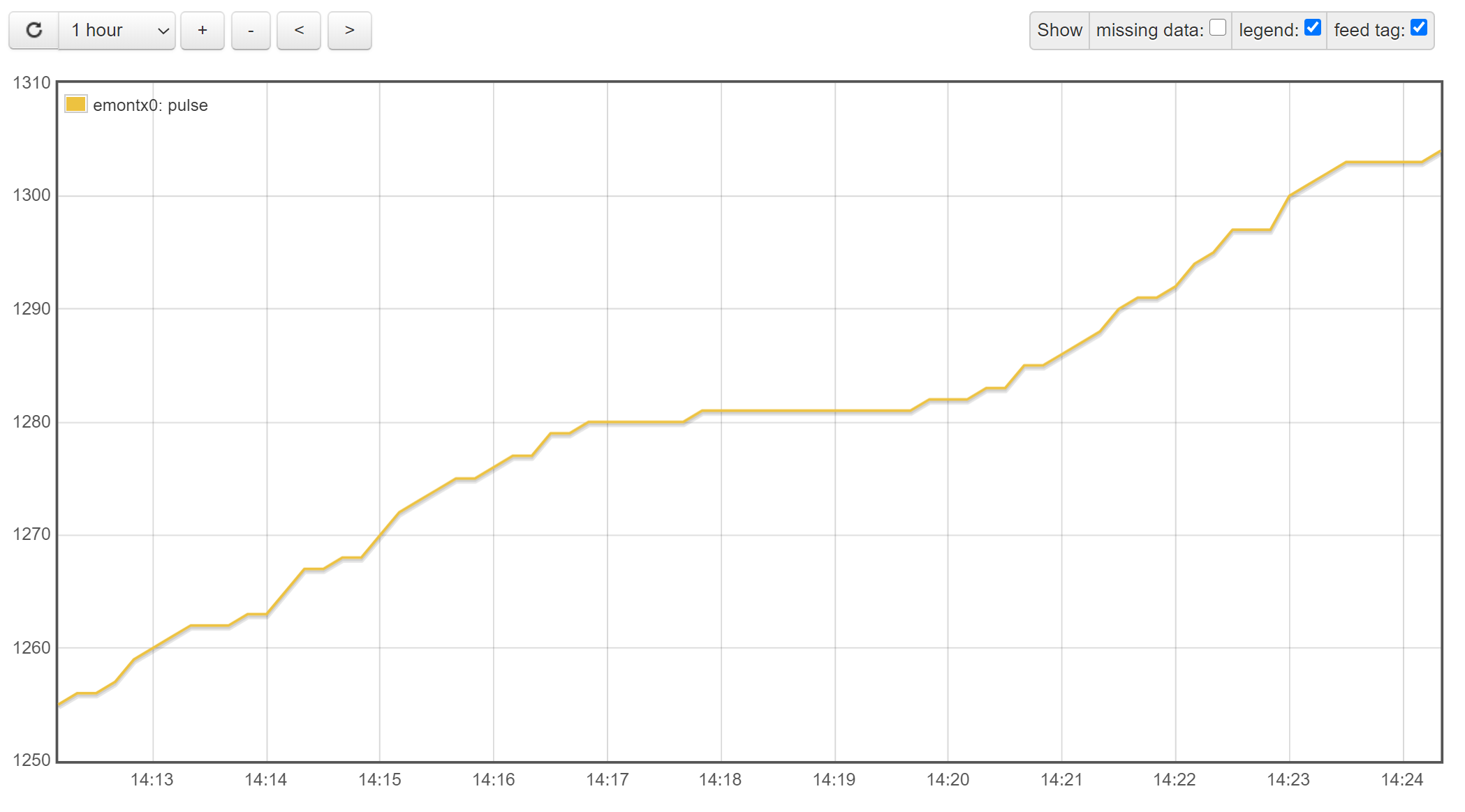
I have recently bought an emonTx kit complete with ESP8266 board, CTs and pulse sensor. Everything is setup and working well but the pulse counter is intermittent, despite the green sensor LED always counting perfectly in time to the meter LED.
The pulse sensor is connected to the emonTx via a 1.5m standard RJ45 extension cable. Am I experiencing some interference/voltage drop that could be causing the emonTx to not count the pulses? Is there a different type of sesnor I could try? What’s the best way to extend the sensor cable that wouldn’t impede performance?
Is the extension wired pin-pin (no crossovers)? Other than that, I wouldn’t expect 1.5 m of extra cable to affect it, even though we know very little about the inner workings of the device.
It’s established fact that the state of the green led on the pulse sensor doesn’t necessarily relate to the state of the output going to your emonTx.
Where is the meter & pulse sensor - are they in a relatively dark place?
Take a look at these threads, they might give you some clues.
From what you have written, I wonder whether the input to the emonTx is remaining HIGH due to ambient light that is enough for that but not enough to light the green LED.
I can confirm the extension is male to female pin to pin - straight through.
The meter cupboard is in a dark place, but I can see through a crack in the cupboard the green LED pulsing at the same rate as the meter LED - but I get the green LED and input to the emonTx are not related.
It’s nothing to do with the extension cable as I can reproduce the same problem with the sensor connected directly (temporarily moved to the emonTx into the cupboard).
Supply voltage between pins 2+5 is exactly the same at both ends of the extension cable - 3.3V.
However, whilst the pulse voltage at both ends of the extension cable is also exactly the same, it is only jumping between 2.2V and 2.6V, so the sensor is keeping things HIGH.
The only way I can get it to come all the way down to 0V is by shining a very bright torch into it - only then is it consistent and counts properly when I wave the torch in front of it.
So, my problem seems to be that my meter LED isn’t bright enough to fully trigger the sensor and pull the pulse output/emonTx input LOW?
It’s a very common Secure Liberty 100 meter.
Could I have a faulty sensor? Any alternatives I could try to get my meter pulse detected properly?
It looks that way, unless it’s connected wrongly (in the RJ45 plug - the wire colours are obvious - red & black the power, blue the output), because the voltage should be HIGH with a bright light on it. (Unless you’re reading down from the 3.3 V? Pin 5 is GND on the RJ45, 3 on the screw terminals is in parallel; the sensor output is 6 and 4; and the 3.3 V is 5 and 2 respectively. I don’t wish to insult your intelligence but it’s been known to get it wrong .)
If everything appears correct, then email [email protected] and mention this thread.
Sorry, yes I was measuring in relation to the 3.3V - so I’m only getting a HIGH between RJ45 5+6 when the light is bright, meter LED not bright enough to trigger, so it’s reading LOW most of the time.
I will fire over an email. Thanks for the help/input.
Your meter type is listed on our meters page, so presumably someone’s had it working. That still means it could be an insensitive sensor, or a dim smart meter. (Sorry, couldn’t resist.)
Yes, but we know the green LED comes on before the output goes high.
If we knew what was inside the sensor, we could make an intelligent guess as to what’s going on. But we have no details other than what we’ve found by measuring two (possibly 3) samples.
This thing is definitely dodgy, I’ve noticed the whole emonTx reboot simply when connecting the sensor directly to it - assuming it’s nothing to do with the RJ45 of the emonTx itself!
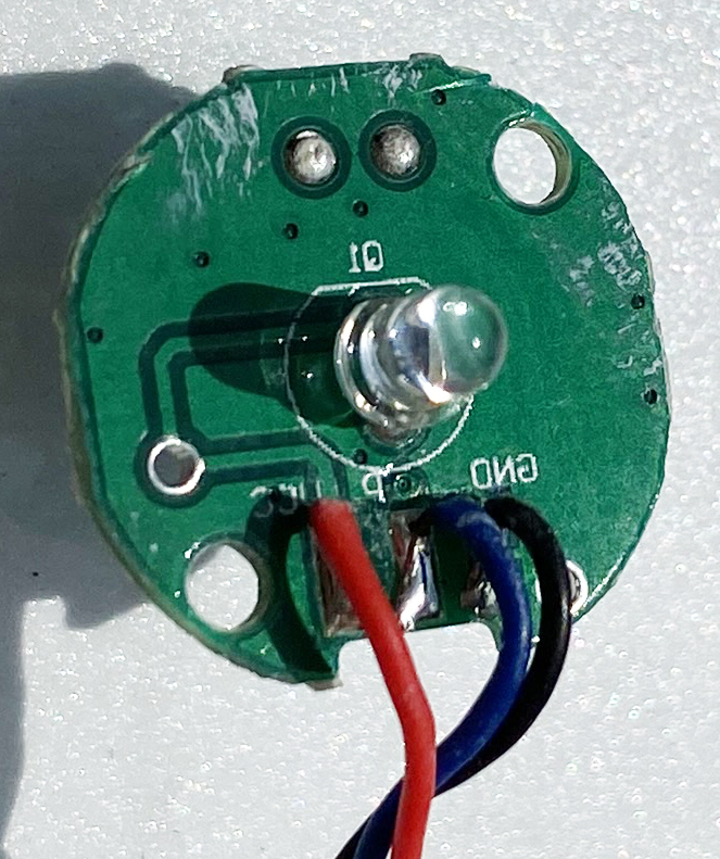
In the name of science I decided to crack it open and just buy another instead.
The first thing I noticed is the silk screen on the sensor side is reversed - and it isn’t your photo! I think there’s enough there to draw the circuit diagram - I might just do that.
The possible reason for restarting the emonTx is C1, it probably dragged the 3.3 V down just far enough to reset the processor.