First try with EmonPi - Pulsecount stuck at 1

I understand what you’re getting at, but the one I tested here put the output to a clear ‘high’ well before there was enough light to get the green LED on, so it’s a fair assumption that there is a pulse on the output wire.

Can @bardal see a pulse on the RJ45 socket, pins 5-6?

and I understand what you’re saying, but “a pulse” requires a level change to be detected and from what you say, it is possible to turn the LED on and off (by varying the light level) without dropping below the “logical high threshold” to register a pulse.

As I have said before, I have been able, to order, get either an led flash with no pulse detected or a pulse detected with no led flash dependent on position alone, this was running at 3.3v using a Pi and the same pulsing LED.

Indeed, it does depend on a decent level of darkness. And you’re absolutely right, with careful control of the light level, the output will remain at a voltage where the input will not go ‘low’ even though the LED is firmly out.

Hopefully, as I mentioned elsewhere, I’ll be able to come up with some numbers. Without that, it’s largely guesswork.

I do think though, that this device has come from a design where some assumptions have been made, and not all of which might be valid in all conditions. It does seem surprising that there would appear to be no means of adjustment for a threshold level.

What’s the best way of testing for a pulse on pins 5-6? Is that plug pins or some pins on one of the boards? I have an ammeter but no scope.

Also, is there a wiring diagram showing how the pulse counter should be wired to the RJ45 plug? I have a stray wire on one side of the plug which doesn’t look right to me.

There’s precious little information available about the pulse sensor, almost everything we know is in this thread, or on the shop page. You can use a voltmeter across pins 5 & 6 on the RJ45 socket - I see 3.28 V looking out of the window, 0.7 V in darkness on an emonTx (3.292 V supply).

The plug on mine is moulded on, with no stray wires, so a photo might help. Can you see how many wires actually go to contacts on the plug, and which pins?

Some measurements:

I used a white LED reading lamp, with several layers of draughting film over the front to attenuate the light. The sensor was therefore looking at a bright but diffuse patch of light approx. 30 mm in diameter.

EmonTx V3.4

Condition Output voltage Distance to light source
Just detecting logic '1' 1.42 V 570 mm
LED just visible 3.28 V 460 mm
LED bright 3.28 V 400 mm

EmonPi

Condition Output voltage Distance to light source
Just detecting logic '1' 1.35 V 710 mm
LED just visible 4.05 V 540 mm
LED bright 4.05 V 450 mm

Observations:

  1. The sensor appears to be sensitive to a wide spectrum of colours, even well into the blue.
  2. It was also very sensitive to light on the edge - i.e. entering between the pair of sticky pads, which seemed totally ineffective at blocking light from the side.
  3. When reading the table, bear in mind the inverse square law.
  4. A Weston light meter read ‘3’ at 570 mm from the light source (~ 35 lux).
  5. It would appear that when used with the emonPi, the output is being clamped by the protection diodes in the Atmega 328P’s digital input circuit. As we don’t know what the output circuit of the sensor is like, this is not good. (@glyn.hudson please note.)

@pb66
It seems quite possible that there can be enough ambient light to hold the output at a logic ‘1’ even though the green LED has gone out; in which case of course no pulses will be detected.
If @bardal sees pulses overnight, that would seem to confirm this is what’s happening.

[Edit - 20 June 2020]
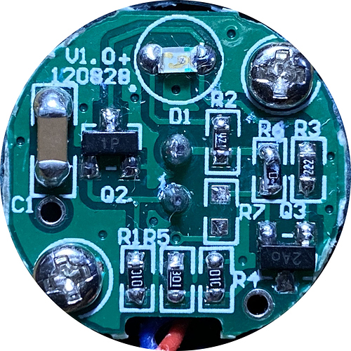
This is the circuit board of the sensor:


And from that the circuit diagram:

Cct Dgm

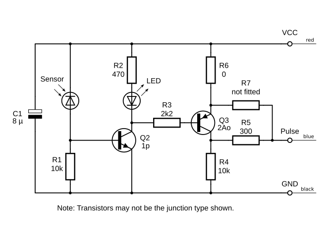
Thanks to @warrenashcroft for providing the photo, and confirming the circuit details.

2 Likes

It’s hard to make out but it looks like the plug has wires into pins 2, 5 and 6.

Indeed, I had to use a hand lens looking on the end of the connector.

Which is as it should be.

So assuming the sensor itself is working, it leaves the possibility either of a fault in your “emon” Atmega328P board, or (as Paul suggests) is it possible that there’s enough ambient light to prevent the pulse input going to a logic low? If your meter is in darkness overnight, the green LED is out and it’s still stuck at 1, the latter seems unlikely.

You can prove whether the board is counting pulses: Unplug the sensor and short pins 5 & 6. If the pulse count moves (it may well jump by quite a few counts), the board is counting.

A slightly more refined test: Do you have a multimeter capable of measuring 5 V d.c. and some fine test prods? If so, you can prove whether it’s the sensor or the board. Measure on the top of the socket itself, the voltage should go quite low (well below 1 V) with the sensor in darkness, and 4 V or thereabouts in bright daylight.

I have just measured the voltage - 3.5V very dark and 4V bright light. I’m not sure if this is the Board or the sensor holding voltage high in the dark.

I will try the shorting test next. Thanks for all the great help!

Ok, I have tried shorting the pins and this has started incrementing the counter. I can’t get the sensor to go below 3.5V so I suspect this is the problem. I’ll order another pulse sensor and see if that gives me some different behaviour.

It looks very much like a faulty sensor. Contact the shop first: email [email protected] and refer to this thread.

1 Like

Ok, so I ordered a new sensor. Performed the same tests, same results!
Shorting still increments the counter, but I can’t get the new sensor voltage below 3.5V!

Confused!

So am I!
What did the shop say?

Waiting to hear back.

Waiting tor 23 days? - give them a nudge.

I only got to test the second sensor today! My delay not theirs.

Guys,

even end completing a script that can be run, where a OPS is directly connected to a RPi.

G

Q3 I think would be a P-type transistor.
If it was, it would be called a high side switching circuit, it’d ensure a voltage close to VCC is seen at Pulse during a high input.

You might be right. In which case it is in straight-forward common-emitter (or common-source) configuration.

I’ve changed the drawing.

Right. I recently made a similar circuit. It was in response to getting stuck at using a single transistor to switch up to a higher voltage. Maybe a single logic level mosfet could be used to simplify this circuit. It at least be a matter of getting the right LDR and mosfet working together.