I think it’s me, but I am about to give up so asking for help.
My SCT-013-000 reads about 104 ohms when NOT connected to anything
My circuit (as described on here) is fed with 5v. The analogue output reads 2.5v, but it reads 2.5v whether the SCT-013 is installed or not. With the SCT-013 fitted around a SINGLE core of a cable with at least 1kw on it, it still reads 2.5v on the analoue output
If I measure the voltage across the SCT-013 whilst in circuit (and bound around a cable) I get a reading of 0v all the time
The signal that the processor sees at its analogue input should always have a DC component of half of the power supply voltage, so 2.5 V in your case. Superimposed on this, there will be an AC component which is proportional to the AC current that is flowing through the wire that the CT is clipped around.
An easy way to establish the AC content of this signal is to run a sketch which repeatedly samples it and displays the content in some suitable way. RawSamplesTool on my Summary Page on the old forum works in this way.
The results will generally be much easier to analyse when a sizeable current is flowing, e.g. when using a 3kW kettle rather than a 40W light bulb.
Okay I am not connecting this all up to any of the computer hardware you have here. I have an old Home Controller called a HomeVision (www.csi3.com). This has a 5v, Gnd, and Analog input on it
So I am wiring the sensing current shown here to those
I don’t understand - as I am not electrical component savvy (good with PCs and mains) - what you mean by superimposed onto the DC
The way I read the analogue port on my hardware is that it will have a value between 0 and 255 (0v - 5v)
The way we measure the current is to use the CT you have, but we measure the voltage across the burden resistor (the CT’s load) around 2500 times per second, and compute the rms current that way. Now unless your HomeVision can do that, we need to think of another way.
The HomeVision website isn’t specific, but all the indications are that the analogue inputs expect only slow-moving values like temperatures, so I think it’s fairly certain that you won’t be able to do anything like what we do here. You’ll need to add a full-wave rectifier and smoothing to your CT’s output to obtain the “rectified average” value of the current, and feed that into your controller.
If you’re interested in pursuing that approach, I can look up some details.
[Edit:]
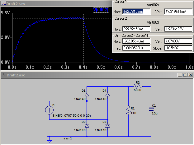
I’ve thrown together a circuit and a quick simulation. I1 is your CT - 0.0707 mA amplitude = 50 mA rms, or 100 A primary current. That feeds a bridge rectifier and the burden resistor (R1) and finally a RC filter removes a large part of the 100 Hz ripple whilst still leaving a reasonably fast response - it reaches the correct output to within 1% in about 260 ms. You can reduce the ripple at the expense of response time. Your 0 - 5 V d.c. output is across C1. Note that this gives the rectified average current, so if you calibrate it with a sine wave, it will be wrong for any other (distorted) wave shape. However, that’s what the majority of budget multimeters will give you.
Thank you VERY much. Yes I was thinking about this over night and came to the conclusion you must be sampling the signal. Homevision may be able to sample 100 times a second, tops, but no quicker
I shall attempt to build this circuit and will report back
I think Robin was presuming you had a faster processor than you appear to have. If you go to Building Blocks, you can see the front-end interface that we use, the theory and maths about how we calculate the rms value, and the sample code that we use. I can think of more complicated and more expensive ways of interfacing to your box, and if you’re keen we could look at some of those. But I suggest you try what I’ve proposed and if it’s adequate for your needs, that’s fine.
I’m building this circuit now. Obviously being stupid. I put my 5v sense, and Gnd across the capacitor. But where do I put my 5v supply, or is no supply needed? I assume the latter
I assumed no power needed, and hooked it up and it seems to work! Fantastic!
I don’t think this will tell me direction of current, as I tried the sensor both ways round and it reads the exact same. Confirm? That isn’t a problem really, as the same computer controls the item that draws all the power (a large air source heat pump), so it will know whether I’m importing or exporting… I think…
This has been working great for a while now. Today though I noticed the sensor reading bouncing all over the place (and it’s raining, and my purchased sensor with display isn’t changing readings). I’m getting 000, 120, 220, 000, etc etc. I read the sensor ever 2 seconds.
I haven’t touched anything
Has something - a component maybe - failed? Any pointers?
To answer the deleted and now resurrected questions:
The circuit I proposed cannot determine the direction of power flow. To know that, you must know the phase of the current in relation to the voltage. There’s a page in Resources that explains this. The emonTx with CT and ac adapter is able to determine the direction of power and energy flow.
If the readings are jumping about, it might be nothing more than a bad connection somewhere. If it’s in the mains circuit, it needs to be corrected urgently as it is a potential fire risk. If it’s in the measuring side, it’s less serious but it should still be investigated and corrected. It could well be that the capacitor has failed. Was it a new component or an old one recycled? The time constant was deliberately made as short as is reasonable in order to provide a fast response, as you can see from the simulation result. Without the capacitor, you’re likely to be reading 100 Hz mains ripple, which is not what you want.
It shouldn’t be necessary to say this, but if anyone is going to embark on an electronics construction project such as this, the ability to make a sound soldered joint is a necessary skill. A properly executed soldered joint will last decades.
Experience with, and/or knowledge of, the following subject matter and tools will help significantly, especially with configuring your system, troubleshooting and calibration.
Linux - modifying scripts, installing software, updating your OS etc.
Raspberry Pi hardware and software environment. e.g. config.txt and commandline.txt
Arduino hardware and the Arduino programming environment - modifying/uploading sketches.
The Python programming language - configuring/troubleshooting emonHub issues.
The PHP and Javascript languages - Modifying and customizing EmonCMS
Applicable terminology. e.g. script, sketch, CT, kWh, VA, etc.
Electronics in general - soldering, using a multimeter, Ohms’ Law, etc.
Basic Radio Frequency theory - calculate antenna length, how RF obstacles affect maximum range, etc.