Power reading about half of true value

Hi,

I have an older Emonpi that I have recently got going again after years of in being pack away.

I have 2 ct clips connected at the fuse board.
No. 1 on the neutral coming from the main RCD (easiest to get a good connection on)
No. 2 on the live for the main socket ring main (both ends)

Both CTs are reading approximately half of the value I would except.

The sd card has emonSD-30Oct18 on it and hasn’t been messed with yet by me. so I assume all the constants are correct. (can’t seem to log in via SSH on my Mac to check. bit of paint to log in locally)

Any ideas?

Thanks
Will

Starting with your version, SSH is off by default. See here to enable it: emonPi SSH disabled by default

Now the power readings.

Do you have the standard UK single phase supply?

Have you got an a.c. adapter? If so, is that showing a roughly correct value for the voltage in emonCMS. If you haven’t, does emonCMS show a constant 230 V?

Are the c.t’s properly closed around the cables - there’s no dust or dirt on the mating faces of the cores? Are the plugs on the c.t. cables fully home?

Those are the obvious things to check. Beyond that, I can’t say that I can recollect seeing this particular problem before, and I can’t immediately think of anything - assuming you have a “factory” version of emonCMS - that could cause the result you are seeing.

Hi Robert,

thanks for your reply.

The first problem of ssh was easily fixed. Thanks.

Uk with voltage from ac plug readying about 229 to 230v today
all readying from emonpi.local/emoncms/
I have check both ct’s. looks good as far as I can tell. I suspect they are fine as there don’t appear to be any randomness in the readings. if I use the kettle both readings go up by the same amount.

I have a emonTH connected which is working fine.

emonhub.conf looks good. is there anywhere else there could be a wrong constant? the error looks to be exactly half the true power value.
thanks
Will

Sorry, I forget to say “Welcome” to you.

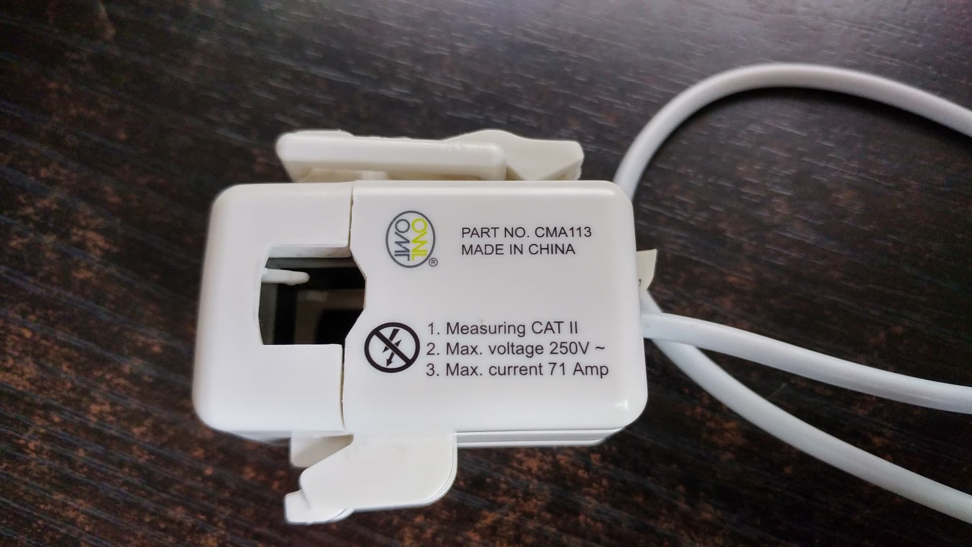
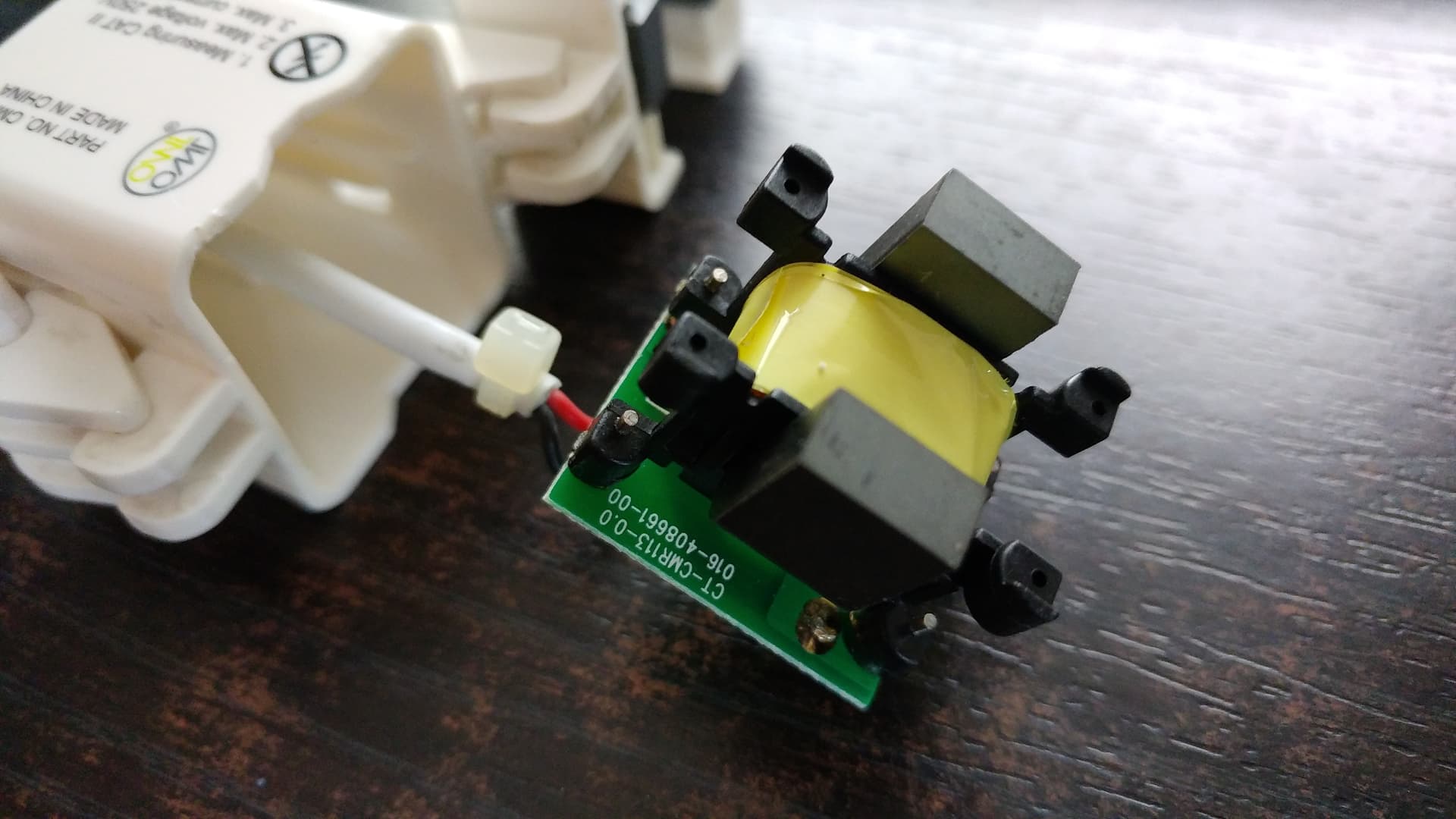
I should have asked another question last time: Which make & model of CT do you have?
If you have anything other than the YHDC SCT-013-000 from the OEM Shop (or elsewhere), then the calibration is going to be wrong. (Note: the SCT-013-000V would give you exactly half-power, because that one has an internal burden resistor, so you’d have two burdens hence half the current in each.)

There are two places where there are “calibration” constants. The real calibration is done in the front end of the emonPi, in the “emon” part. This is actually a stripped-down, 2 channel emonTx in most respects, so everything about how the emonTx is calibrated applies to that.
There’s a second place where you can do a partial calibration, that’s in emonhub.conf (accessible via the web browser and the emonHub page). It wasn’t intended for calibration, so the full calibration isn’t available there; but emonhub.conf is easily accessible.

My first thought was you’d got “USA” mode set. This changes the front-end voltage calibration to read 120 V instead of 240, and uses that in the power calculation. But as you’re seeing the correct voltage, that’s not it.
The second thought was you had a 3-phase supply, and if the a.c. adapter was on a different phase to the c.t., you’d also get exactly half-power with a resistive load, and probably nearly so for most other things. But few UK dwellings have a 3-phase supply (though that might change as everyone gets EVs).

And if you’ve not changed anything in emonCMS (including emonhub.conf), I can’t see the calibration in the ‘emon’ part being wrong. And besides, it’s quite hard to get at - except for the ‘USA’ switch.
You can easily check the scale constants in emonhub.conf, the set of values for the emonPi itself looks like this:

[[5]]
    nodename = emonpi
    [[[rx]]]
        names = power1,power2,power1pluspower2,vrms,t1,t2,t3,t4,t5,t6,pulsecount
        datacodes = h, h, h, h, h, h, h, h, h, h, L
        scales = 1,1,1,0.01,0.1,0.1,0.1,0.1,0.1,0.1,1
        units = W,W,W,V,C,C,C,C,C,C,p

Yours might not be exactly the same (that’s the 2019 version) but all the “scales = …” values are either 1, 0.1 or 0.01, and you’d need a “0.5” in the first two or three to get half-power.

One thing I would strongly advise: update your emonCMS to the present version, emonSD-08May21. We can’t maintain “old” versions indefinitely, and as you’re just starting, you won’t have the problem of migrating your data when you’re forced to update later on. I have the latest running on a RPi 2B (it’s just a bit slow showing a big graph), so the age of the emonPi isn’t a problem.

Hi,

I am a new user of the emonPi. I have a 230V grid and I used a CT I had from another Energy Meter (OWL) which has the following specs:

250V
71Amps

I too see half of the real power (I tested it in a electrical boiler where I know that the load is 4KW) The input shows exactly half the power. CT is connected to one of the two power cables and I tested both Neutral and Line with the same results. I use the latest stable version of your EmonSD (July '21 I think).

I have to say though that I created a custom Jack to connect the CT. I used a stereo Audio Jack where I have connected the black cable of the CT to the Ground of the Jack and the other one (RED) to one of the two “channels” of the audio Jack. Is it OK? I did it because the CT had a coaxial connector.

I checked EmonHub.conf and voltage is correct (230V) also the scales (1,1,1)

I have also connected the AC-AC voltage sensor adapter.

What other should I look into ? Any ideas ?

Welcome to the OEM forum, Nikolas.

You need to know the ratio of your Owl c.t.
The YHDC c.t. that we recommend has a ratio of 100 A : 50 mA. (In the UK, the ratio of a c.t. is specified as two currents - the rated primary current to the secondary current.) Inside the emonPi, we have a 22 Ω burden to convert the current into a voltage for the ADC to measure. You need to know the secondary current that your 71 A rated primary current generates.

That is probably correct - if it was wrong, you’d see a very small or no power - just a few watts. We use the tip and sleeve connection of the plug - no connection to the ring.

When you know the c.t. ratio, you can calculate the calibration constant so that the emonPi reads the correct power. The constant that you need is the primary current that will give 1.0 V at the ADC input. If you don’t want to correct the constant (Using Admin → Serial Monitor to send the appropriate calibration command), which is the “best” way to do it, then you can adjust the “Scales=…” value in emonhub.conf - but only the individual power values can be correct with this method, power1pluspower2 will most likely be incorrect (because the values are added before the number is received by emonHub).

Hi Robert,

thanks for the quick reply. So I will try to find out the ratio of the CT. Just in case I will succeed in finding the ratio, could you please tell me the commands to correct the calibration?

I did change the scale to “2” so to double the read out but it doesn’t seem like the correct way to do it. Moreover, I noticed that when I switched off the load I still had a indication of 1W in the input. I suppose this is also an outcome of the uncalibrated CT.

The commands are listed when you type ? (and send it, of course).

Not necessarily - remember that the calibration “out of the box” gives a design maximum power of 24 kW, so 1 W represents a tiny percentage error.

Well,

I enabled the terminal and send the “?” to see the availble commands but although I see the Cal values for the two power ports (CT) I can’t figure out where is the command that changes them.

emonPi V2.92
OpenEnegMonitor.org
startup...
LCD not found
CT 1 Cal: 90.90
CT 2 Cal: 90.90
VRMS AC ~256.83V
AC Wave Detected - Real Power calc enabled
Vcal: 256.80
Vrms: 230V
Phase Shift: 1.70
Detected 1 CT'sDetect 1 DS18B20
RFM69CW Init:Node 5 Freq 433Mhz Network 210

Available commands:
  <nn> i     - set node IDs (standard node ids are 1..30)
  <n> b      - set MHz band (4 = 433, 8 = 868, 9 = 915)
  <nnn> g    - set network group (RFM12 only allows 212, 0 = any)
  <n> c      - set collect mode (advanced, normally 0)
  ...,<nn> a - send data packet to node <nn>, request ack
  ...,<nn> s - send data packet to noe <nn>, no ack
  ...,<n> p  - Set AC Adapter Vcal 1p = UK, 2p = USA
  v          - Show firmware version
  <n> q      - set quiet mode (1 = don't report bad packets)
OK 5 0 0 0 0 0 0 122 93 85 0 0 0 0 0 0 0 0 0 0 0 0 0 0 0 (-0)
OK 5 0 0 0 0 0 0 116 93 85 0 0 0 0 0 0 0 0 0 0 0 0 0 0 0 (-0)

It looks as if you don’t have the software version that supports changing the calibration on-line - I thought it had been published but apparently not.

You can still download the sketch from Github and change the calibration constants in the sketch, but then you need to compile it, load the compiled file into the emonPi and then transfer it into the Atmel '328 “shield” where the power is calculated.

Changing the “scales=…” in emonHub is much easier, even though I agree with you, it does not seem to be the ‘correct’ way to do it.

Hi Robert,

It’s OK, if you point me to the ino and the line where I have to put the new calibration values. I think I can flash it through Pi or I can connect directly to the UART pins of the Emon.

The sketch is multiple files in Github: GitHub - openenergymonitor/emonpi: Raspberry Pi Based Energy Monitor. Hardware, Firmware & related software for the PI. and you need “Firmware”, NOT ATMega 328 which is obsolete, but it appears impossible to mark it as such or remove it.
The values are in lines 91 & 92 of src.ino. (The number is the current to give you 1.0 V at the ADC input, similarly the voltage calibration.)
The instructions to load the compiled sketch are Hardware Technical Wiki→ Uploading Arduino Firmware

Thank you Robert. I will try to make something of these or I will just quit and consider buying your CT :slight_smile:

If you have, or can borrow, a multimeter that reads mA a.c., then it’s very easy to measure the secondary current. If you can read the load current with another ammeter at the same time, so much the better.

WARNING: Do not leave the c.t. open-circuit while current is flowing. A c.t. can always be short-circuited in complete safety, you can damage a c.t. by leaving it open-circuit without a burden (unless your c.t. has an internal burden and is therefore the ‘voltage-output’ type).

Connect your 4 kW load and measure both currents. If the secondary current is small, you can wind the load wire through the c.t. many times to multiply the primary current - don’t go above 71 ampere-turns (3 turns should give you 50 - 55 At - should be OK). Then the ratio is the primary ampere-turns to the measured secondary current.

Hi Robert,

I really appreciate your help and guidance.

Well, I took some pictures of the CT.


The thing is that I have 3 of them. That’s why I wanted to use them.

As you can see, there is nothing on the transformer/pcb mentioning anything besides the model name. I managed to find the documents submitted for the CE/FCC approval but they didn’t mention specs for the CT.

There is a resistor but it’s on the primary not the secondary. Is this right ?

I do have a couple of multimeters. To be honest I was planning to use a small load (around 1.5KW) to make some measurements and comparisons with the OWL so to see how much the deviation is.

So what you suggest is to connect the CT clamp to a load. Connect in series a multimeter to the Load and another one (in series) to the CT secondary (meaning in series with one of the cables leading to the connector jack) and measure the currents at the same time. The problem is that the load wire in the distribution panel is very thick so I won’t be able to do turns on it if needed so.

Anyway, it’s a nice “exercise” no matter the outcome :slight_smile:

No, that is in fact a burden resistor on the output - the secondary (the primary winding is the cable you put the c.t on), so your c.t. is actually a voltage-output type - and if I can see the colours correctly, it is 100 Ω (brown, black, black, black, gold = 100 × 100 ). That is part of your problem, because your emonPi also has a burden inside it - 22 Ω. So the effective burden is 18 Ω.

NO, in parallel with that 100 Ω resistor. Remember, a c.t. itself is a current source - so everything you understand about voltage sources (batteries, lab & computer power supplies) has to be turned around. You can safely short-circuit a c.t. - and then it’s delivering zero power. You must not leave it open-circuit, because then it tries to deliver infinite power by generating an infinite voltage in an effort to drive some current into nothing - and it can damage itself like that.

Depending on what you measure, it is possible to modify your emonPi and change the internal burden resistor. It is the big surface-mount resistor immediately behind the socket, with a hole at each end ready for you to add a wire-ended resistor. As we’re likely to want less than 18 Ω, you’ll need to take the SMT resistor off and only have a (new) wire-ended one. We can calculate the value when you’ve measured the c.t.

Aha! OK got it !

Yes indeed, it’s a 100 Ω resistor. I have a set of wire resistors so If I finally take the measurement I may be able to find one that fits.

So, I can measure the current in parallel like I do in a power supply with overcurrent protection.

OK then I have to setup cabling and load and take the measurements.

In the mean time I will also upgrade the firmware to the microcontroller.

Thank you once more for being patient and helpful.

It’s me again.

Well, I tried to get the measurements but I didn’t succeed.

1st try

Connected a multimeter is series with the load and measured 5.75A at the same time I tried to take measurements from the CT (I haven’t it connected to the emonPi or the OWL since it has a resistor in the secondary and therefore it has a load). I tried two multimeters in ACA set at 20mA and 200μA. It gave me nothing. The probes were connected in parallel with the 100Ω resistor. I tried to make 1 cable round and a second and again the reading were zero.

2nd Try

This time I connected the CT to the OWL so to be able to see if it works and the readings. Without additional rounds it gave me 1.37KW, with one round of the cable I got 1.8KW and with a second round gave me 2.7KW. Afterwards I connected again the multimeter in parallel with the resistor of the CT and again I got nothing. Zero current. My assumption is that my (cheap) multimeters aren’t sensitive enough in such low currents although they do have the scales to measure even μΑ.

Anyway, I will try the calibration workaround through emonhub.conf.

For your info, I compiled and loaded firmware 2.93 in the ATmega328 but again I can’t see the calibration commands.

Are you sure you can actually measure mA & µA a.c? - because a.c. current ranges that low and “cheap” don’t usually go together.

Your next best thing will be to try to measure the a.c. voltage across the 100 Ω burden, and deduce the current that way.

What do you have here:

You should be seeing
const float Ical1= 90.9; // (2000 turns / 22 Ohm burden) = 90.9
const float Ical2= 90.9;
float Vcal_EU= 256.8; // (230V x 13) / (9V x 1.2) = 276.9 - Calibration for EU AC-AC adapter 77DE-06-09

Those are the two current and voltage calibration constants, which you can edit (and then compile and load).

Hi Robert,

I have two “working” multimeters. Both are very old (one of them 30 years old…) One Metex M-3620 and one Tele GM-389. Both have ACA scale down to 200μΑ. They are multimeters in the range of 10-10-15EUR so…

Well, I ordered a Uni-T [UT139C] which I think will be able to measure small currents like those we have here.

As for the calibration commands it’s my bad. I thought you meant that your have implemented a command which I could sent through terminal and change the calibration values without recompiling the firmware. Yes I have seen these values in the code.

Ohm’s Law will be my guide here. I will try again as soon as I receive the new multimeter. The old ones don’t have my trust anymore :stuck_out_tongue:

Thanks for your help once more :slight_smile: