The article correctly notes that emitter temperature will be maximised when flows in the primary and secondary circuits are roughly equal (i.e. no short-circuiting in the buffer tank). However, it does not take into account the additional pump energy required to increase the flow in the secondary loop. I made a few calculations to include this effect, and observed that total energy required may be higher with equalised flows.
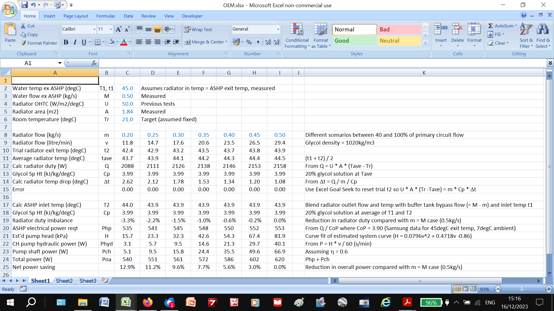
For those with 20mins to spare, take a look at this screenshot of my spreadsheet:
The input data are typical of my setup, but with varying secondary loop flows. (A trial-and-error intermediate calc is needed to match U.A.dT with m.Cp.dt over the emitters, but Goal Seek solves this easily.)
The spreadsheet clearly shows that the radiators will indeed be warmer at higher secondary flows (row 11 and 19) per the HeatGeek article, but when the CH pump energy is included (rows 22 and 23) the total power required is higher at higher flows (row 24).
[In fact, my CH pump only has 3 selectable speeds/flows rather than true variable speed per the calcs, but the principle remains the same.]
For me, the lesson is to make sure that all effects are included when optimising performance.
If anyone wants the actual spreadsheet to look at their own setup, here it is: OEM.xlsx (13.9 KB)
You would NEVER use a 4-pipe buffer with a secondary that has HIGHER flowrate. You would use a 2-pipe volumiser.
You WOULD use a 4-pipe buffer if the secondary needs to operate at a higher dT that the heat pump due to pipe sizing limitations. That would be definition be a lower secondary flow mate than the primary though?
Not totally academic. My system (as set up on installation) had a secondary flow just over half the primary, and based on the Heat Geek article (thanks to Ian C for bringing it to my attention) I was about to increase the secondary flow when I did the calcs and discovered that doing so would actually increase my power requirement (so I’ve stayed at the lower flow).
I was just making the point that users may not get the full story from external sources (even respected ones like Heat Geek) without thinking things through fully, especially where results might appear counterintuitive.
But I totally agree that you would never have a higher secondary flow than primary.
Very interesting. I’ve been wondering if I should try messing with the pump speed of my two-loop system, but hadn’t considered there might be additional consumption by the pump.
Linking to this related post by @Rachel where she’s matching the ΔT on both sides of the low-loss header by adjusting the pump speeds:
Assumed to run at 45C flow / 43.9C return in the default scenario. Wowser. That’s a tiny deltaT. And a high temperature for such a low overall power output from the rads.
Old fixed circulator units were expected to operate at say 55/47C at full output, 45/40C at part output, and 35/32C at minimum output. (do the numbers on a radiator sized for 8C and 55/47 at full chat and those mass flowrates should give you 5C and 3C dT at lesser flow temperatures.
The 5C dT was about the right balance between compromising your heat pump efficiency (higher flow temp required for a given radiator output) and burning too much on pumping power.
The 8C and the 3C were side effects of fixed speed circulators. Variable speed circulators can target a deltaT rather than a flowrate.
Your scenario of 45/42.5 at 0.2 kg/sec is more like what you’d expect to design to. Reducing the primary flow is probably what you want to be doing here; subject to the heat pump being small enough to work with that. (should be - 12L/min is still decent enough for a modern unit); and piping the buffer in as a volumiser?
Isn’t there also a question of what happens to the energy you put into the pump? My secondary pump is inside the house envelope, my primary pump isn’t. So energy inefficieny in my ssecondary pump ends up heating my house, as does much of the extra pumping energy put in through frictional losses in the pipes (not inside the envelope I really want to keep warm) and in the radiators and especially rad. valves where I think there is quite a pressure drop. So presumably a good proportion of the energy going into the pump ends up heating the house at a CoP of 1?
One of the advantages of my variable speed control, which will have a positive impact, even if I’m not convinced the better delta T control will, is that the pump speeds ramp down when the delta T falls, so when the system is running in ‘anti-freezing’ mode (mine keeps the pump running), it will be doing so at minimum energy input. Since implementing the control, my ‘off’ load is about 10W before it was about 55W.
Hi Marko.
I have to run my LWT high because of high heat loss from the living room (3 walls and half the ceiling are exterior), and there’s not much radiator area. I’ve already optimised the weather compensator for this, so the only other variables available are the circulation and CH pump speeds (both have three selectable fixed speeds). The CH pump was on minimum, and I thought the circ pump was too, but (as a result of your post) I just checked and it’s been on medium speed (my installer must have reset it last time he was here). So I’ve dropped it to minimum again (now 70% of my spreadsheet value) and will now re-monitor the system. Thanks for the nudge…
Sarah
Very good point you make about heat loss location, but unfortunately my buffer tank and primary/CH pumps are in my garage, so heat lost there doesn’t help my living room .
I haven’t got my head around the benefits of deltaT control, but the engineer in me wants to minimise it provided the additional pumping costs are negligible. Am I missing something?
Minimising does seem sensible, but if you look at the (very long) Anyone Monitoring Ecodan R32 thread, you will also find that John Cantor’s analysis says that the Ecodan performs better when you have a DT of around 5C. Below that it seems to do some erratic things. It’s certainly true that my heat pump is a bit more stable with the DT controlled, but whether that’s borne out in improved performance I don’t yet know and may not really find out as I’m operating it in a different way (I’m optimising against Octopus Agile, which is defintely much cheaper) to my last year of operation. I might try running for a week at a DT of 3 or 4 in the new year and see what that looks like.
You run your MWT high because of those limiting emitters not the LWT.
It’s the mean water temperature that dictates radiator output rather than the supple temperature.
Bigger deltaT means reduced pumping energy. But bigger deltaT means increased flow temperature for a given radiator mean water tempeature. Heat pump efficiency suffers.
Moving from a 20C dT to a 10C dT materially reduces the supply temperature for a given mean water temperature. Moving to 5C dT is another improvement. Moving to 0C your pumping energy becomes infinite - there’s some sweetspot here between pumping cost and heat pump cost.
It’s usually in the 3-8C region. The product test standards assume 5C so if you assume vendors have optimised to ace the tests 5C should probably be what you’re aiming for but it would make an interesting experiment to see if 3, 2, or 1C improve matters.
This is independent of the mean water temperature that you require for the limiting emitters. Perhaps you even run those with a smaller deltaT than the others to bump their output marginally for a mean deltaT that’s still 3C or 5C?
Yes, but a smaller radiator deltaT maximises its average temperature thus duty for any given inlet temp (i.e. LWT), and that’s what I’m trying to minimise with my weather compensator temp profile. I know my emitters are limiting, but despite getting an unimpressive CoP, my ASHP consumption at 0degC outside is about 25kWh - that’s about £8/day - and we don’t get many days that cold here. So there’s not a big incentive to enlarge my radiators (or festoon the hardware with monitoring gear).
I can’t help feeling that the target 5degC deltaT is based more on tradition than economics and Chemical Engineering…
If I’m looking at the right post, I interpret John’s stability problems as condensation in the compressor at deltaT < 5degC, which could be vendor-specific.
I’ve been running with no noticeable problems on my Samsung at 2degC deltaT, but it hasn’t dropped below -2degC ambient since installation yet (and I’ve now increased deltaT to 3degC by reducing primary loop flow rate). I’ll post how things go next time we have a severe frost…
There’s a balance between pumping electrical energy and heat pump COP. Too much volume flow or and/or too high a pressure head will chew pumping energy. This skews more in favour of pumping too much now that we have efficient pumps.
There are pipe velocity limits. Too fast and they’re noisy (in addition to needing too much pressure head); too slow and you can struggle to get air and dirt out of a system. This skews in favour of higher velocities/pressure drops now that we have variable speed pumps. One only needs the noise occasionally.
There are differential pressure limits. Regular vanilla radiator valves get noisy much beyond 0.3 bar pressure drop (3m head, or the middle sweetspot of a typical 6m head circulator) and regular zone valves won’t hold much byeond 0.6 bar pressure drop. Units with built in circulators are usually built around this.
Evidently there are control issues with some units at low dT. Old school fixies with wax bulb TXVs needed a healthy superheat in some/most conditions in order to avoid low superheat at extreme conditions. Newer units are playing games with electronic expeansion valves and temperature sensors on pipes/refrigerant pressure sensors. Perhaps if the dT is too low the temperature sensor/pressure sensor inaccuracies can cause control issues.
With a teeny tiny heat loss relative to the size of the distribution pipework perhaps you can indeed get away with hosing the water through at a high volumetric rate for the emitter area but not a particularly high vleocity or pressure drop. With larger heat outputs (e.g. 6 rads and 1 kW per rad at full chat) you do hit pipe velocity limits at lower dTs.
Now I have my pump PWM controller working nicely, i can see that my secondary pump is a bit undersized.
I’m wondering about replacing it, but am struggling to find any 8m head pumps that actually allow control via PWM, let alone ones that are the right dimensions to fit! (Needs to be a direct swap for a Grundfos UPS3)
I have a DUCA APE25-8-130. I haven’t yet connected up the PWM but that’s on my todo list.
Has the following settings I II III, Constant Pressure I II III, Proportional Pressure I II III, and AUTO. Would be nice if it had a knob like the Wilo Pico to set the exact flow you want.