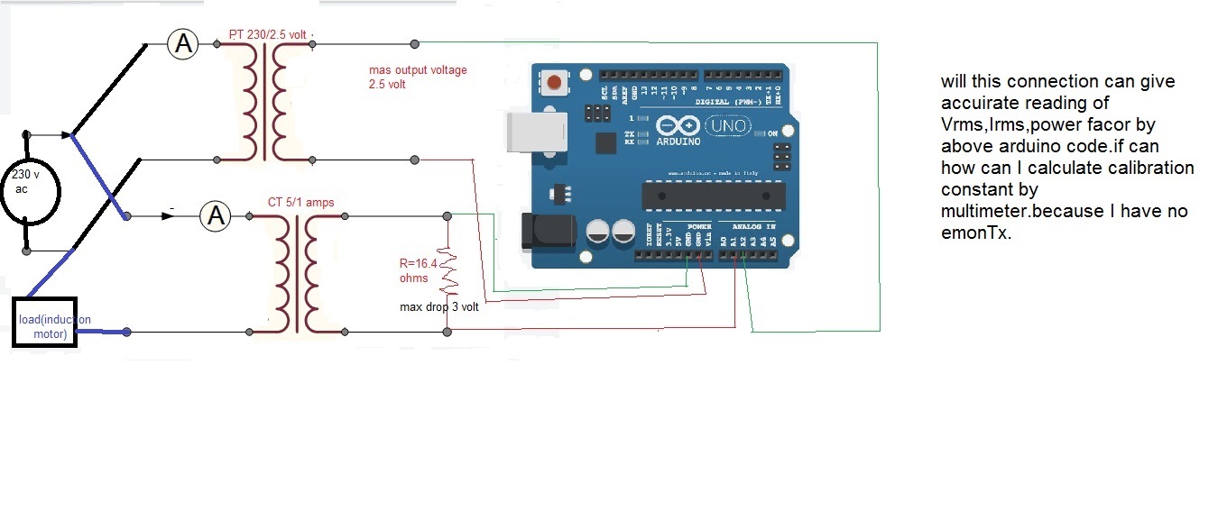
I’m using 230/2.5 volt PT and 5/1 amp 15 VA CT to step down voltage and current respectively.and using two 8.2 ohms 2watt resistor in series across CT to get voltage drop corresponding current.this two parameters are fed to arduino analog pin A2 and A1 .so what will be the calibration values and phase sift emonlb.h related program.
IF I WANT TO CONNECT TO DIFFERENT SYSTEM IN A SINGLE ARDUINO WHAT WILL BE THE “PHASE SHIFT” FOR 2ND SYSTEM IN THIS COMMAND " emon2.voltage(4, (primary voltage/secondary voltage), ?); "
Here is the program
#include "EmonLib.h"              // Include Emon Library
EnergyMonitor emon1;              // Create an instance

void setup()
{
  Serial.begin(9600);

  emon1.voltage(2, 234.26, 1.7);  // Voltage: input pin, calibration, phase_shift
  emon1.current(1, 111.1);        // Current: input pin, calibration.
}

void loop()
{
  emon1.calcVI(20,2000);          // Calculate all. No.of crossings, time-out
  emon1.serialprint();            // Print out all variables
}
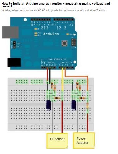
You will find a full explanation and everything you need to calculate the calibration coefficients in Resources > Building Blocks.
Bear in mind that the circuit design examples assume that your P.T. will give approximately 11 V on no-load, therefore with a 2.5 V transformer you will need to adjust the voltage divider resistors to give you about 1.6 V rms at the Arduino input, likewise your burden resistors need to give you a similar voltage at the maximum current you want to measure. If your maximum motor current is 5 A, I think those resistor values are wrong.
I cannot begin to guess the value for phase calibration, as it depends greatly on the characteristics of your transformers. You need to follow the calibration procedure to find the correct value.
Sir I can’t understand why my PT will give approximately 11 volt at no load? My PT can give 2.5 volt for max input 230 volt.why I need 1.6 volt rms? I think I can apply (0<v<5) volt into the arduino analog pin.
Besides I’m failed to find phase shift calibration procedure.please give me any link or something.if I use proper calibration constant will this circuit connection work properly on the above Arduino code.
You did not understand me. I wrote that the circuit design examples (see the two sections "Non-invasive ***** measurement") in Building Blocks assumed an 11 V output from the a.c. adapter, which defined the voltage divider ratio. That is when using a 9 V transformer because without a load, a small transformer will give you typically 20% higher voltage than the label says. You need to design your voltage divider circuit likewise - I do not know the exact voltage you will see from your 2.5 V transformer, but I would guess between 2.8 and 3.2 V.
You need a maximum of 1.6 V rms at the input pin of your Arduino so that you have an undistorted version of the mains wave for emonLib to use for the calculations. This applies to both the voltage and the current inputs.
Here is the calibration theory and here the exact procedure.
[So that we can organise this information better, can you say why you did not find those pages?]
sir please don’t mind I’m new learner of arduino
you mean I have to take care of the arduino analog input pin voltage not more than 1.6 volt (rms) both for voltage and current at any cost to gate the undistorted version of the mains wave for emonLib to use for the calculations?
1.sir,one thing I can’t understand the phase shift calibration.
2.and I want to attach multiple system like A1-V1,A0-I1 ; A3-V2,A2-I2 ; A5-V3, A4-I3 like that. then can I use emonlib.h as emon1,emon2,emon3?
3. if 2nd no is possible how I can measure phase sift constant for V1,V2,Because we know arduino will read data first A1 then A0 than A3 then A2 then A5 then A5 (if I will wire code in this sequence ).
That is correct.
Every transformer introduces a phase error - the input and output waves are not quite in step. The arduino can only make one measurement at a time, so there is a time delay between measuring voltage and current. Those three things together give you what we call “phase error”. By doing maths on the voltage readings, we can compensate for these effects. That is phase calibration.
Yes, you can do that. You set up three “instances” of the class EnergyMonitor - you can call them emon1, emon2 & emon3, and then you initialise them with the pin numbers for your connections;
emon1.voltage([your voltage pin, calibration constant, phasecal]);
emon1.current([your current pin, calibration constant]);
… and likewise for the other instances.
You set the phasecal constant by testing with a resistive load (a heater possibly) and keep adjusting the value (and reloading your sketch) until you get a power factor as close to 1.00 as possible.
1.sir maximum how much current can fed to arduino analog pin.because our Atmega328p-pu micro controller is heating and after some time it damaged.
2.another problem is after calibrating the voltage,current and phase error by attached resistive load it is not give proper pf for another load.
3.My ct give max output 1 amps and pt give 750 mA it may be very high current. so I want to step down those current at 40 to 60 mA without changing ct and pt.
or
by the above circuit I have destroyed already 7 to 8 Atmega328p-pu micro controller.please give me any protection circuit.
in this circuit pt o/p current is 750 mA ,voltage 1.3V (Vrms) and ct o/p current 700mA,burden resistance 1 ohm.
in this above circuit why capacitor is used??is those capacitor is must??
That depends on which pin you are talking about. Generally, is specified in the Data Sheet, which you can download from the Atmel website. For the analogue I/O pins, it is specified in a general “family” data sheet. I don’t have a link, but there’s a discussion about this on the old forums, which a search should find.
How do you know that? What is the “other load”?[quote=“nabin_bera, post:8, topic:441”]
3.My ct give max output 1 amps and pt give 750 mA it may be very high current. so I want to step down those current at 40 to 60 mA without changing ct and pt.orby the above circuit I have destroyed already 7 to 8 Atmega328p-pu micro controller.please give me any protection circuit.in this circuit pt o/p current is 750 mA ,voltage 1.3V (Vrms) and ct o/p current 700mA,burden resistance 1 ohm.
[/quote]
Your thinking here is wrong. It is likely that you are destroying your processors by feeding a voltage that is lower than 0 V, or higher than VCC. YOU MUST NOT DO THAT. This is why I wrote a day or two ago that the rms voltage that you feed must not be greater than 1.6 V rms, and it must be fed via the bias circuit in Building Blocks.
The reason for the bias circuit and the capacitor is explained on the pages in Building Blocks about measuring voltage and current. All the questions that you have asked so far are explained in Building Blocks, and if you had looked a these, it might have saved you the cost of the 7 or 8 processors that you have now destroyed. You can carry on experimenting if you want, but I think you will learn a lot more, and more quickly, if you read through the Building Blocks pages about electricity monitoring.
thank you sir. I’ve understand all the things.
how much error in percentage can come between actual value and arduino output?
That is examined in detail in Building Blocks. After careful calibration, some users have claimed better than 1% agreement with their tariff meter.
During phase calibration can I use electric blub as a unity power factor load In spite of heater?
You should ideally use a load that comes closest to the load you will see in normal use. A single lamp is unlikely to give you that. Do you not have a space heater, electric kettle, or similar?
I’ve a electric kettle.
Sir can you help me about matlab program?
Sorry, I know nothing about Matlab.
Sir I have got power factor and voltage by arduino is not so satisfactory.suppose my pf meter gives .347 but my arduino gives value between .33 to .35.and voltage has almost +10 error for induction motor and +2 or +3 error for blub load.why this type of fluctuation is coming?Is this the calibration error or others.
What does this mean: 10 digits error, 10% error, or 10 × error?
in multimeter if it shows 190 volt arduino shows almost 200 or 210 volt for induction motor.
But for bulb load is shows almost 195.
 Sir.
Sir.