If anyhow I can contact you by live chat.it may be helpful for me.because I have lack of time to submit this project.
Actually sir I’m from India.electrical engineering ,b.tech student,This is my first time I am learning and also working on programming.Before This I never learn
any types of programming language.
Those numbers can mean two things. Either that you have a very weak supply, and the load is changing the voltage that you measure, or in your Arduino, the current measurement is affecting the voltage measurement. You must calibrate your Arduino to read the same as your meter without the motor connected. Then if you connect the induction motor and it loads the supply so that the voltage drops, and you still read the same voltage on the Arduino as your meter, your supply is weak. But if the voltage that the Arduino reads is different from your meter, then you need to check the wiring of your voltage and current transformers.
is it universal?I mean is it work for any system after one time calibration???
The Arduino, when working properly and calibrated, should behave exactly the same as a Voltmeter, an Ammeter and a Wattmeter, because these are the things it does when you measure voltage and current and from those calculate power. You do not recalibrate your multimeter when you use it in different places, and you do not need to recalibrate your Arduino - provided that you always use the same voltage and current transformer and the same d.c supply voltage to operate it.
Can you please explain how emonlib.h work to calculate energy related parameters. Because I can’t understand the code in the emonlib.h file.
emonlib.h is a header file containing the declarations. The calculations are done in emonlib.cpp
There are comments in the file that explain the purpose of each step, and the details are explained in the various Building Blocks articles.
If you have difficulty in understanding the C++ language that this is written in, then there are very many on-line tutorials.
My bible for C is of course “Kernigan & Ritchie” http://www.amazon.co.uk/C-Programming-Language-2nd/dp/0131103628/ref=sr_1_3?s=books&ie=UTF8&qid=1292502807&sr=1-3. This is the standard text book.
The normal place I point people at who want to move up to C++ is http://www.relisoft.com/book/index.htm and that assumes you know C. Because the Arduino environment normally uses a very small subset of the language, neither are the best place for a beginner to start, nor are many of the other on-line tutorials. I’d still suggest you have both of those, and maybe Bruce Eckel’s “Thinking in C++” http://www.planetpdf.com/developer/article.asp?ContentID=6634 available for reference.
However, there is this: Home | Mechanical Engineering | College of Science and Engineering which does look to be a good starting place for a beginner. It does not go as far as classes and methods that are used here, though. For that, you need the Relisoft course.
when actual power factor is .22 or .23 or .24 … like that then this program showing power factor is .78 or .77 or .76 … like that.means it shows 1-actual power factor.Why it is happening??
I do not believe that it is reading (1 - (power factor)), unless you have changed the software. The maths is the real power is calculated by taking the set of voltage and current samples multiplied together and then taking the averaging; the apparent power is calculated by multiplying together the root mean square values of current and voltage; and the power factor is simply the real power divided by the apparent power. So unless you have changed emonLib, I cannot see how that could possibly happen.
You can have very wrong values of real power if your voltage and current transformers have phase errors that are very different from each other, and you also have very wrong values of real power if you set PHASECAL to a value outside of the recommended range.
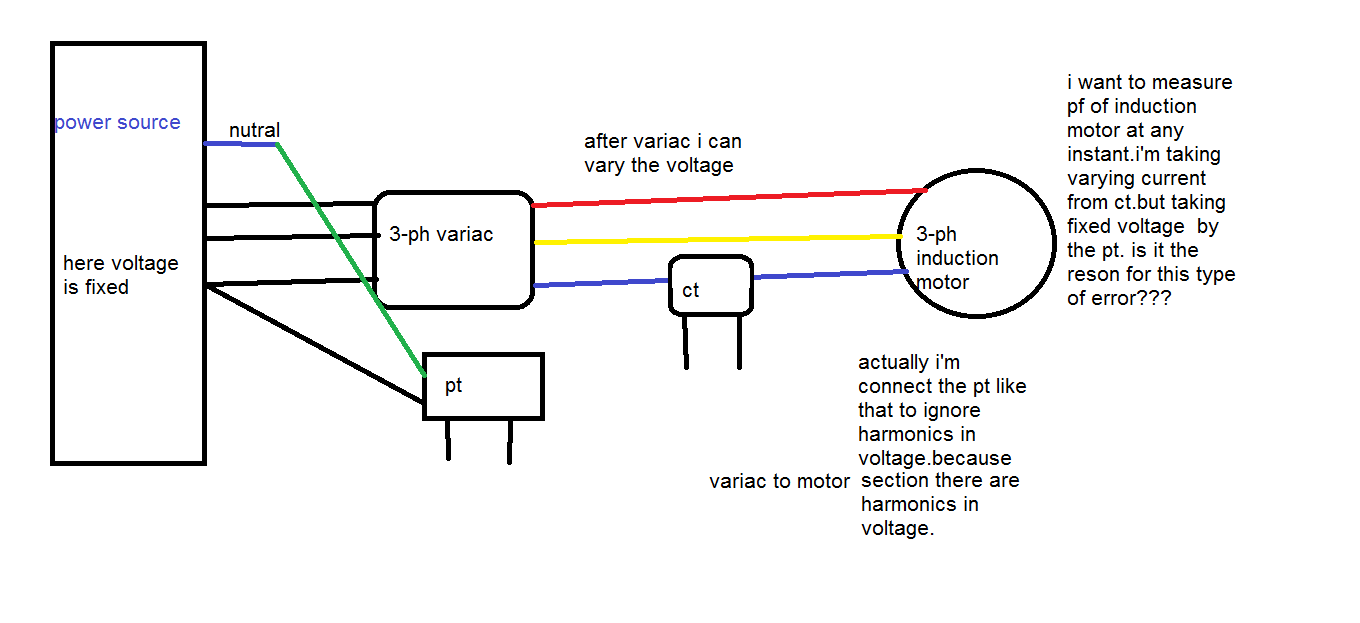
What you have done there is to introduce another phase error into the calculations - the phase error of the variac. What do you think the effect of that will be? Do you know what the phase error is, and is it always the same or does it change, and if so what causes it to change? These are the questions that you should be asking.
More questions that you need to ask yourself: What are you trying to measure there? The power and power factor of the motor with the variac, or the power and power factor of the motor on its own? What you have is neither of these.
I have never measured the phase error of a variac, but I’m quite happy to believe it will not be zero.
If you have a twin-beam oscilloscope available, you can use that to check how much voltage distortion and phase displacement the variac introduces.
can harmonics in the voltage signal effect the pf value???
If there are harmonics of the same frequencies in the current, yes.
Try entering “harmonics & power factor” into your favourite search engine.
You should really be asking your tutors to explain things like this, because they can give you a much fuller answer.
Actually sir I wanted to ask can harmonics in the voltage signal effect the pf value in this arduino based system.
The answer is the same. Look at the maths that emonLib uses, and look at your textbooks regarding power measurement. The only limitation will come when the harmonics are outside the measurement bandwidth of your Arduino. It could be instructive to try to calculate that, then, as your college probably has the apparatus to do so, to verify your calculations by measurement. You can then, as you’re learning to become an engineer, use your judgement to decide what the error in your power factor measurement might be. (What I’m asking there is, how much power do you think there might be in the harmonics that you can’t measure? And is it significant?)
I know no load power factor of 3-ph induction motor is .197 to .3.but my Arduino system shows sometimes out of this range sometimes in this range.in this reason I’m thinking it may be for the reason of harmonics.
we know active power or real power =vrmsIrmspf.
but arduino calculate it by taking the set of voltage and current samples multiplied together and then taking the averaging.how this is equal?I think it is instantaneous power.
But the rms calculation is just a mathematical device to find a number that represents the average power that gives the same heating effect as a direct current (or voltage) of the same value.
The average instantaneous power is the true calculation (assuming the instantaneous values are recorded at equal time intervals - which is indeed the case).
Do the maths in a spreadsheet and you can demonstrate to yourself that you get the same value, whichever way you calculate it. But for simplicity, only do it with a sine wave.