I bought a wifi relay switch on July, but only today I connect it to my heat cylinder.
Everything seems to work, except there’s no current output.
The relay seems to work well, with a nice sound ON/OFF.
I already checked the onboard MST250 fuse (in and out circuit), and it’s working well (i used a multimeter).
I do not have one of these, but I have looked at the documentation. It is very confused. The old 3-channel unit had two terminals for L & N in, and three sets of two terminals for L & N out.
Relay’s 3 contacts (NO-C-NC) are now available and not tied to AC
That to me says that you need to find out how to connect the relay. There are two ways:
Disconnect your board from the electricity supply and look at how the output terminals connect to the relay and to the mains.
Disconnect your load and measure the voltage between all 3 output terminals - two at a time, and between the supply N and each output terminal, all with the relay both energised and de-energised. If all of those measure a very low voltage ( < 5 V), then use your meter on Ohms and check continuity between the centre output contact and the other two, with the relay both energised and de-energised. I am guessing that will show that the centre terminal connects to one of the other two when the relay is energised, and the third one when the relay is not energised.
If the Wiki ‘To Do’ is correct and that change has been done, then depending on how you found out what the connections are, you need to
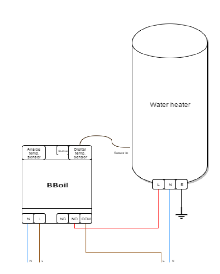
link the mains L in to the terminal that connects to the pole of the relay (possibly marked “common”), then take a wire from the terminal that connects to the relay terminal that’s possibly marked “n/o” to your load, then the N from your load to the “N” of the supply
or 2. link the mains L in to the centre terminal, then take a wire from the terminal that showed a connection when the relay was energised to your load, then the “N” from your load to the “N” of the supply.
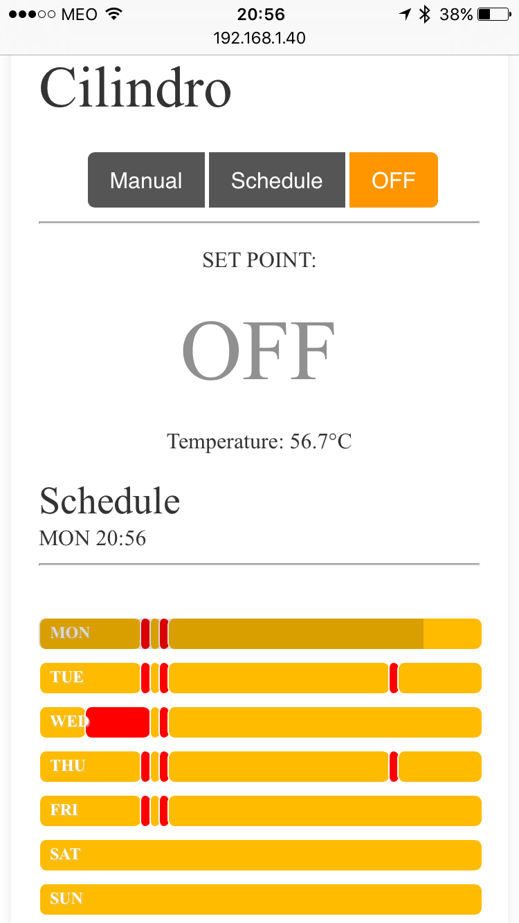
I did some measurements, and I have exactly the same values when the relay is ON or OFF.
The closest value I have is 192V, measuring the N from source and the first (left side) of the three contacts from output, but it not depends on the relay status.
Can anyone from OEM team send me some info on this matter? How I connect this to a output machine?
I’ve PM’d @glyn.hudson, and I think he should know, and if not he is better placed to contact @Martin_Harizanov who is the source of these units.
I think the 192 V is “pick-up” - capacitive coupling between the mains and the other wiring, but without taking the pcb out of the box and looking at it and tracing where the tracks go, I cannot be sure. I shall not tell you to do something that might be dangerous to you or that might damage the relay board. Until someone from the shop replies, the only safe way is to disconnect everything, dismantle the box and look and check with an Ohmmeter.
Thanks for letting me know, I think this is something for @Martin_Harizanov to look at, he knows the relay unit better than anyone (being the designer!). I will drop him and email to point him to this thread.
I seem to recall that he’d moved towards having voltage free contacts, instead of the original ‘live out’, so that they could replace home thermostats/controllers, but could be wrong.
the second approach will provide AC voltage to the load, while the first one will simply disconnect the phase as a normal switch. you chose which wiring method suits you best.
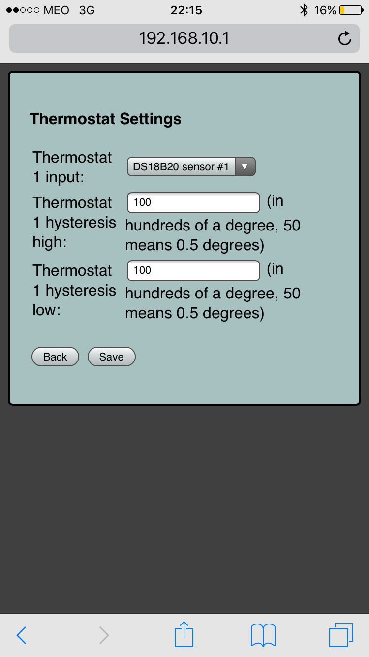
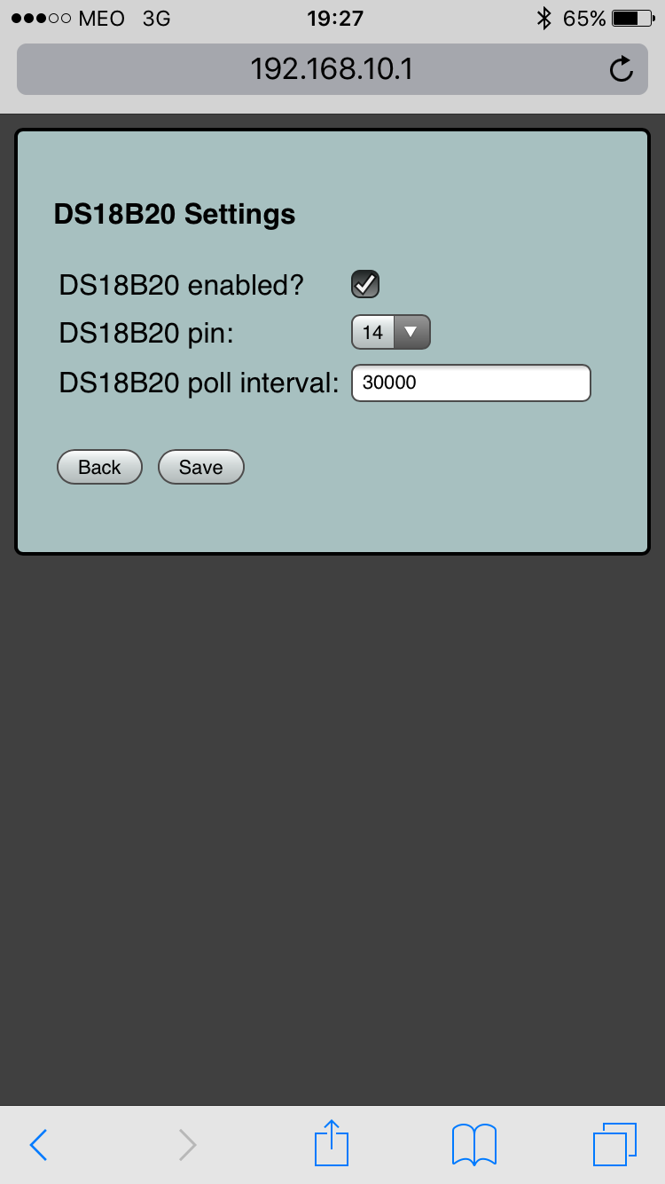
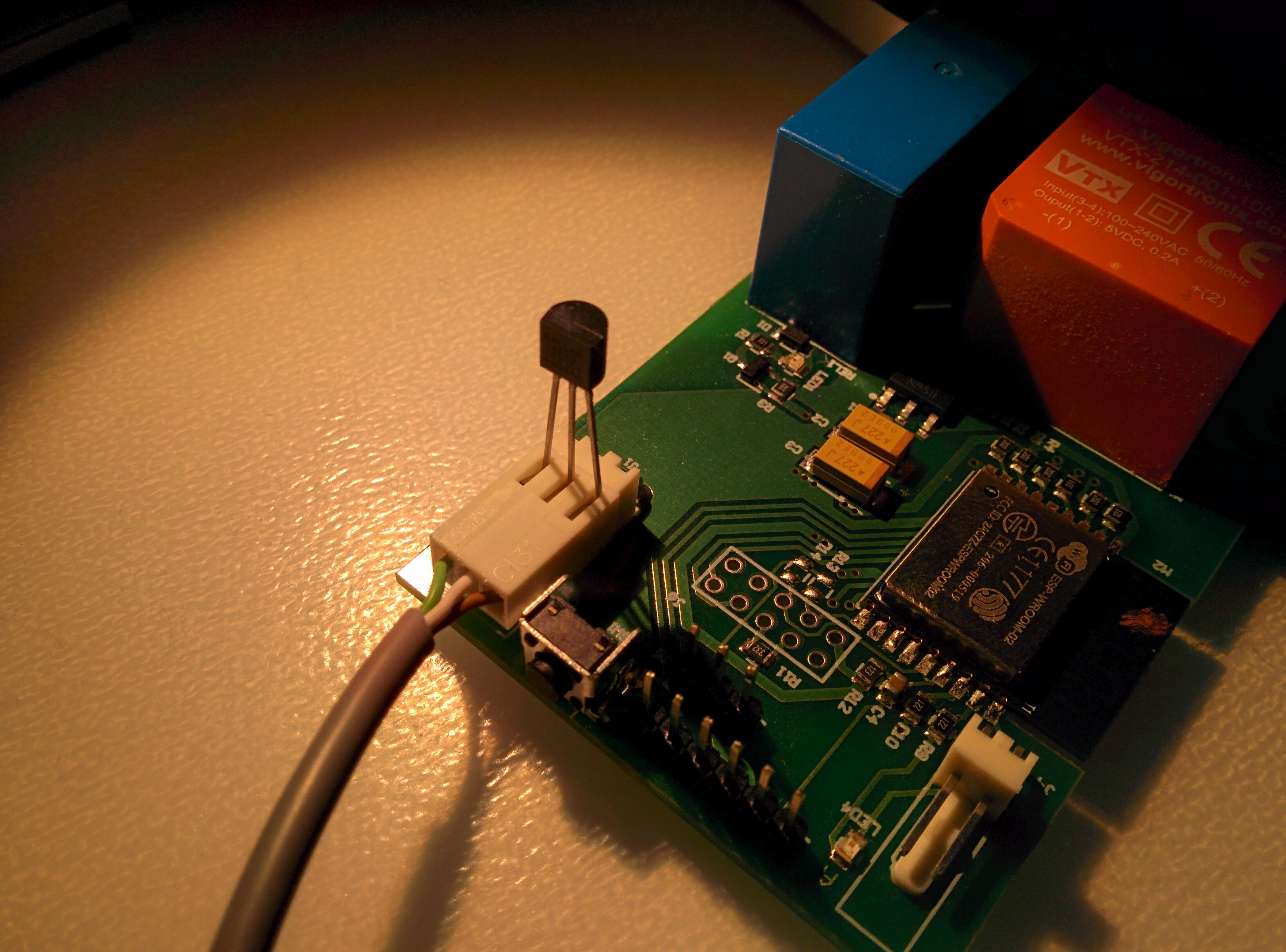
The temperature sensor isn’t providing reading; can you share your DS18B20 settings page and double-check the wiring of the sensor? Did you modify/extend the temperature sensor wire?
Settings look fine, so it is most probably the sensor playing tricks… If you pull it hard enough, the wires may get detached from the socket on the wire side…
Do you by chance have a spare DS18B20? If so, just insert it like this to test and eliminate wiring issue: