Newbie - what sensors do I need?

Hello everyone.

I’ve just managed to get hold of a bare emonTx v3 & power supply secondhand. Now looking to add the necessary peripherals to monitor my home (single phase) setup.

Specifically I’d like to figure out how much of the PV-generated power we use domestically and how much is exported to grid. In the hope of ultimately sizing a home battery once we can afford it.

We have a solar edge inverter, a MyEnergi Eddi diverter and two separate SunAmp heat batteries which store excess PV generation for hot water use.

I have a couple of years’ worth of data from the Eddi and SolarEdge which tells me how much we are diverting into each battery and how much PV energy we generate overall. But most of the rest (e.g. where the non-hot-water electricity goes) is extrapolation and conjecture from our mains meter.

I figure I need at least two CT clamps (100A?), an optical pulse meter for the mains, possibly a voltage meter and I’ll need to either buy or build a compatible emonbase. Any other hardware suggestions would be greatly appreciated.

Welcome, Tom, to the OEM forum.

First, a question - is the emonTx power supply a 5 V d.c. USB one or a 9 V a.c. adapter? Because the latter can also function as a power supply, and having one will mean you can know the direction of power flow as measured by the c.t’s. You don’t know this without the a.c. adapter, its prime function is to measure the voltage, both to know the direction of power but also for accuracy, as our UK mains voltage varies quite a lot.

The second, maybe obvious, point is the optical pulse reader is of limited use on your grid meter, because you only get pulses on import – you know nothing about the energy exported. It is however very useful as an aid to calibration.

As a minimum, I suggest you need a c.t. (probably 100 A) on your main grid connection, and one - possibly a smaller one for better accuracy (we can recommend some, but they might mean adding or removing a resistor inside the emonTx). You’ve then got 2 channels left - if you have room inside your consumer unit you could consider putting a bundle of ‘similar’ circuits through each to give you a better idea of where “the rest” goes.
If you have a pulse output on your generation meter, you could use the optical input on that (the power consumed 'dark" is normally below about 15 W, so barely significant in the overall scheme of things) and free the channel for something else.

An emonBase is a Raspberry Pi - running on an identical SD card to the emonPi - but equipped with a radio receiver. But, if it can be close to the emonTx, you don’t even need the radio and you can use a direct serial connection.

As a matter of some importance when you’re looking for a sketch for your emonTx, which V3 is it - V3.2 or V3.4? The V3.2 has the processor on a sub-board (RFµ328) piggy-backed on the main p.c.b, with the radio module on that, while the V3.4 has the processor directly on the main p.c.b.

Robert,

Thanks for the detailed reply. To answer your questions/points in order:

  1. The power supply is labelled 9V AC, so it sounds as though this can be used to measure the voltage

  2. We have two meters, one is for mains grid import, the other is for total PV generated at source (e.g. not a measure of how much is exported). It sounds like using the pulse reader on the generation meter is the best option.

  3. I’ll definitely get a 100A CT for the mains. Please can you suggest an appropriate size for the second clamp?

Due to the way the Eddi diverter works, I already have 2 CT’s (1 on the mains grid and 1 on the PV supply) so that it can prioritise using surplus PV energy for the hot water. Assuming that CT’s don’t interfere with each other, I had planned on putting the emonTx clamps next to the existing ones.

I guess that I could just use the remaining two slots for CTs on the supply cables to each of the heat batteries so that it can measure what amount of the total has been diverted to these. The remainder would give an overall domestic use but nothing finer grained. Would that be sensible? Diagram below, slightly edited to reflect my setup.

  1. I have a spare Pi Zero W but I’m assuming this is not capable of reliably being used for emonBase. Can you advise what model of Raspberry Pi I’d need to get hold of to build one that is compatible with my version of the emonTx?

  2. On that note, I probably jumped the gun with this post - the V3 won’t get delivered until later this week so I can’t check the exact version yet! I’ll update this thread once I know more…

Yes, it will automatically be doing this.

Agreed - but you can also use it to help calibrate your c.t’s (temporarily, before transferring them to their intended position).

What is the maximum current you’ll be measuring? Your c.t. wants to be not less than this, with a small margin above for safety. Bear in mind (this probably won’t apply to your P.V. infeed, certainly not to your water heating) inrush currents and power factor if you’re thinking of things like fridges etc with induction motors, or a lot of fluorescent or LED lamps.

Input 4 of the V3 (both 3.2 & 3.4) has a high sensitivity input intended for a P.V. infeed when used with the standard (OEM Shop) YHDC SCT-013-000 c.t., so you can use this. For the thermal store, you probably will want one or two of the Talema range from RS Components (why two? - if they are energised separately, put the c.t. inside the Eddi with both line conductors going through, this inherently gives you the total)
My note says:

UK c.t’s 25 A / 40 A / 50 A: https://uk.rs-online.com/web/p/current-transformers/7754909 or /7754903 or /7754912 Secondary 50 mA, good to 1.6 V. (Ignore ±400 A Output, it’s wrong.)
https://uk.rs-online.com/web/p/current-transformers/1243897 50A:50mA (good to 1.6 V)
https://uk.rs-online.com/web/p/current-transformers/1243896 25A:50mA (good to 1.6 V)

With a stereo 3.5 mm plug fitted (extending the wires if needs be), they will directly replace the YHDC one, all that’s needed is a change to the calibration.

They can interfere if they’re touching, but 20 - 30 mm gap should be fine.

@borpin - Can you say yea or nay to this please?

Thanks again for responses.

The thermal batteries are separated physically (one supplies main bathroom & kitchen, one does en-suite), but they are also fed by separate outputs from the block. Please see lower right ‘HEATERS’ in image below ‘borrowed’ from the internet. So I think I have to use separate sensors unless there’s a clever way to do a double-clamp just after they have left the diverter?

Each cable is 16A rated. So 25A CT for each?

Since I definitely want to know what proportion of our usage is PV, I think CT clamp 2 has to be on the PV infeed. This cable is 16A also.

It should work OK as long as you don’t expect too rapid a response if pulling lots of data into a chart. For simple analysis and collection of data it’ll be fine to start with.

I thought I’d told you this - you might need to strip the cables back a bit, but it’s perfectly in order to put 2 line (brown) wires through one c.t., and it will measure the vector sum of the currents. As both are on the same phase, and both are resistive loads, that should give the total power.

Don’t be tempted to use one line and one neutral, the neutral will read the power but negated, so you’ll read the difference - and if the energy is shared equally - little or nothing!

Hello again. So I now have the emonTx and can remove the cover. The board is labelled v3.4.2.

Can you tell me what this affects? The type of sensors I can use, or something more fundamental?

Only the sketches you use. It’s only the emonTx4 that uses different sensors, all the previous versions (V2, V3.2 & V3.4) use the same 9 V a.c. adapter for voltage and the same YHDC SCT-013-000 current transformer (or the Talema range I mentioned above).

Hello,

It’s been a while as I’ve been buying the sensors and looking for a Raspberry 3B+ to act as the emonBase (now on its way). I wasn’t certain that a complete newbie like myself wouldn’t encounter issues with trying to get the Zero W to work properly.

From what I’ve read, I’ll therefore need to buy an RFM69Pi module to connect to my emonTx3, but I don’t understand how the two communicate if there is no RF module on this board. Can someone explain how the Pi receives the signal? Is it just over Wi-Fi instead?

For context I’m aware I could connect the two directly with a cable, but based on where I have free power sockets and strong wi-fi signal, it’s likely I’d position the RPi some distance away from the Tx3.

To conclude my current equipment list is as follows:

  • emonTx3 v3.4.2 with voltage reading power supply
  • 2x SCT013 20A CT clamp (1 for incoming PV and 1 for MVHR circuit)
  • 1x SCT013 100A CT clamp (incoming mains)
  • 1x RS Pro 25A CT sensor (combined thermal batteries)
  • Raspberry Pi 3B+ with SD card and power supply

I’d appreciate pointers on anything else that would be necessary/advisable for this setup.

Thank you

Which is “this board”? Your emonTx V3.4 already has a UHF RFM69CW ISM-band radio on board – in the picture 2 posts above, it’s the green module and the antenna socket is the brass part next to it. (You do have the antenna that goes with it?) The RFM69Pi module plugs into the Raspberry Pi and receives the transmissions from the emonTx. This radio link can be loosely described as a connection, it’s not Wi-Fi.

The Raspberry Pi communicates with your laptop/desktop by Wi-Fi or wired Ethernet.

Thank you Robert. I was talking about the RF module or ‘expansion board’.

There are 2 versions of the RFM69 available from the shop:

  • RFM69Pi no RF “receive and send data via wireless from older hardware (pre 2022) e.g emonTx V3”

  • RFM69SPI “receive and send data via wireless from other 2nd generation hardware e.g emonTx V4”

I understand that I need the older hardware version, but since it is described as “no RF” I took that to mean it doesn’t use radio like the newer version.

So I was just wondering what it meant by “wireless” in this context. As in, does it still communicate on a certain radio band or does it use my domestic Wi-Fi network.

From your description above, it sounds like there is still a radio link on the expansion board, not Wi-Fi (and presumably not 433 MHz frequency either).

I do have the antenna, so once I buy the RFM69Pi I’m hoping I’ll have everything I need.

Thanks.

“No RF” is an abbreviation - it means no RF module is fitted and you have to buy the RFM69CW separately and solder it in yourself. That’s what you need if you’re using your emonTx V3.4 as it came, because from the description of the “SPI” version, it comes with the LPL radio library software which your emonTx V3.4 won’t by default be using with the original default sketch.

However, the LPL radio library can be used in your emonTx V3.4, somebody (not me) has done a version using emonLibCM (which I thought you’d mentioned you wanted to use, but I can’t see it) which would enable you to have a more secure radio link and maybe importantly, it’s a bit more future-proof if you expand your system later; and in this case, you want the “SPI” version of the RFM69Pi. You’d need to be able to upload the new sketch to your emonTx, I believe the RPi is capable of this if you have the latest emonCMS loaded, though I’ve not tried it.

Hello again.

After some delay ordering components etc. I’ve now set up my emonBase and can log in successfully via emonpi.local. This allowed me to update the Tx3.4 firmware via a UART cable to the latest version, so I think everything is now up to date.

However my emonBase can’t seem to ‘see’ the emonTx, which I think may be because I went for the SPI version of the RFM69 module. When I go to the Inputs page they all say “n/a NULL”

Robert’s reply above suggests that I should be able to upload a different sketch to the emonTx so that it can use the LPL radio library. Presumably that needs to be done via UART cable since it can’t talk over wireless?

Can anyone point me towards the place to find this software, and ideally a guide to uploading it onto the Tx? Is it the same process as for the firmware update?

This probably means you’re either using the wrong settings in emonHub (part of emonCMS in your emonBase RPi, or you’ve sent the wrong sketch with the wrong library to your emonTx. It doesn’t necessarily mean you have the wrong hardware - in fact it’s probably the correct hardware but the wrong mix of software.
As far as I’m aware, the SPI version comes with the LPL library, which you can have, but might not have, in your emonTx

Look at the emonHob log - is there anything there suggesting you’re getting anything from your emonTx? Which sketch exactly did you send to your emonTx?
(I’ve been almost totally involved with emonLibDB, so I haven’t been able to keep abreast of all the other changes that have happened in parallel - and nobody at Megni tells us about all the changes, we’re expected to find out, how I don’t know.)

I started to write more, but realised that without knowing exactly which sketch you might be using in your emonTx, there were too many permutations to cover.

Thanks for the quick response Robert.

             Programmer Type : Arduino
              Description     : Arduino
              Hardware Version: 3
              Firmware Version: 4.4
              Vtarget         : 0.3 V
              Varef           : 0.3 V
              Oscillator      : 28.800 kHz
              SCK period      : 3.3 us

There are entries in the log with varying values for CT1 and the VRMS, and there is mention of the LPL interfacer too (apologies for the text dump below), so perhaps there is a connection, but it doesn’t publish to the Inputs page.
NOTE the input is defaulted to emonTx4, even though it is a Tx v3.4 - I haven’t found a way to edit this:

2023-11-05 10:47:04,209 INFO MainThread Opening hub…
2023-11-05 10:47:04,209 INFO MainThread Running as user: pi
2023-11-05 10:47:04,210 INFO MainThread Logging level set to DEBUG
2023-11-05 10:47:04,210 INFO MainThread Creating EmonHubOEMInterfacer ‘EmonPi2’
2023-11-05 10:47:04,212 DEBUG MainThread Opening serial port: /dev/ttyAMA0 @ 38400 bits/s
2023-11-05 10:47:04,214 INFO MainThread Creating EmonHubOEMInterfacer ‘USB0’
2023-11-05 10:47:04,216 ERROR MainThread Could not open serial port: /dev/ttyUSB0 @ 115200 bits/s (retry every 10s)
2023-11-05 10:47:04,218 INFO MainThread Creating EmonHubRFM69LPLInterfacer ‘SPI’
2023-11-05 10:47:04,243 INFO MainThread Creating RFM69 LowPowerLabs interfacer
2023-11-05 10:47:04,243 INFO MainThread node_id = 5
2023-11-05 10:47:04,244 INFO MainThread network_id = 210
2023-11-05 10:47:04,244 INFO MainThread Starting radio setup
2023-11-05 10:47:04,270 INFO MainThread Radio setup complete
2023-11-05 10:47:04,272 DEBUG MainThread Setting SPI pubchannels: [‘ToEmonCMS’]
2023-11-05 10:47:04,274 INFO MainThread Creating EmonHubMqttInterfacer ‘MQTT’
2023-11-05 10:47:04,276 DEBUG MainThread Setting MQTT pubchannels: [‘ToRFM12’]
2023-11-05 10:47:04,276 DEBUG MainThread Setting MQTT subchannels: [‘ToEmonCMS’]
2023-11-05 10:47:04,277 INFO MainThread Setting MQTT node_format_enable: 0
2023-11-05 10:47:04,277 INFO MainThread Setting MQTT nodevar_format_enable: 1
2023-11-05 10:47:04,278 INFO MainThread Setting MQTT nodevar_format_basetopic: emon/
2023-11-05 10:47:04,278 INFO MainThread Setting MQTT node_JSON_enable: 0
2023-11-05 10:47:04,279 INFO MainThread Creating EmonHubEmoncmsHTTPInterfacer ‘emoncmsorg’
2023-11-05 10:47:04,281 DEBUG MainThread Setting emoncmsorg interval: 30
2023-11-05 10:47:04,282 DEBUG MainThread Setting emoncmsorg pubchannels: [‘ToRFM12’]
2023-11-05 10:47:04,282 DEBUG MainThread Setting emoncmsorg subchannels: [‘ToEmonCMS’]
2023-11-05 10:47:04,282 WARNING MainThread Setting emoncmsorg apikey: obscured
2023-11-05 10:47:04,283 INFO MainThread Setting emoncmsorg url: https://emoncms.org
2023-11-05 10:47:04,283 INFO MainThread Setting emoncmsorg senddata: 1
2023-11-05 10:47:04,284 INFO MainThread Setting emoncmsorg sendstatus: 0
2023-11-05 10:47:04,284 INFO MainThread Setting emoncmsorg sendnames: 1
2023-11-05 10:47:04,285 INFO MainThread Setting emoncmsorg compress: 0
2023-11-05 10:47:04,286 DEBUG MainThread Automatic configuration of nodes enabled
2023-12-30 09:53:10,609 DEBUG USB0 Opening serial port: /dev/ttyUSB0 @ 115200 bits/s
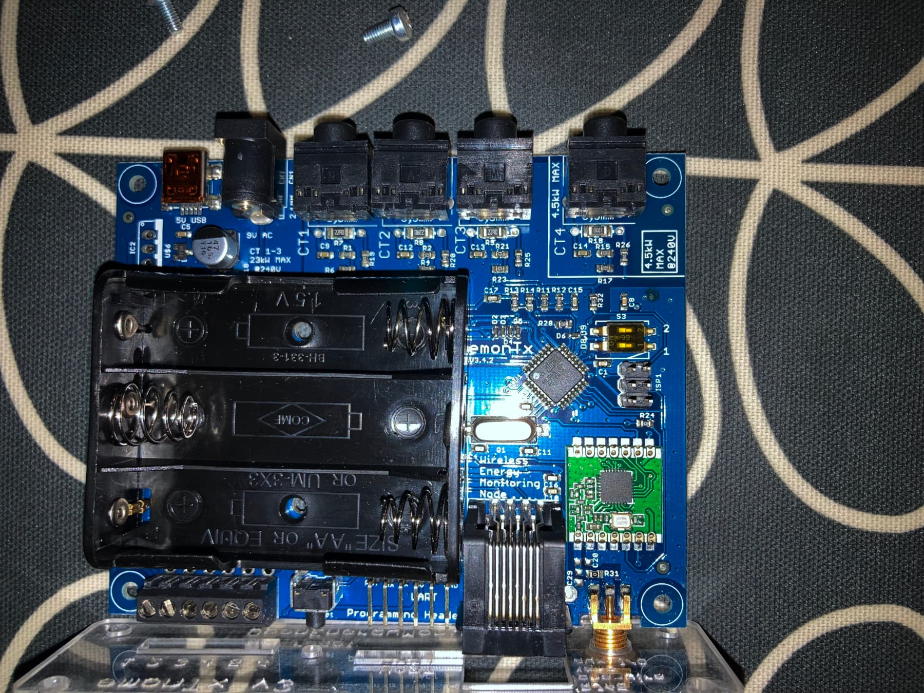
2023-12-30 09:53:22,752 DEBUG USB0 CT 1 Cal 90.90
2023-12-30 09:53:22,855 DEBUG USB0 CT 2 Cal 90.90
2023-12-30 09:53:22,957 DEBUG USB0 CT 3 Cal 90.90
2023-12-30 09:53:23,060 DEBUG USB0 CT 4 Cal 16.67
2023-12-30 09:53:23,766 DEBUG USB0 RMS Voltage on AC-AC is: ~6V
2023-12-30 09:53:23,872 DEBUG USB0 AC-AC NOT detected - Apparent Pwr measure enabled
2023-12-30 09:53:23,975 DEBUG USB0 Assuming VRMS: 230V
2023-12-30 09:53:24,081 DEBUG USB0 Assuming power from batt / 5V USB - power save enabled
2023-12-30 09:53:24,184 DEBUG USB0 NO CT’s detected
2023-12-30 09:53:24,287 DEBUG USB0 No temperature sensor
2023-12-30 09:53:24,391 DEBUG USB0 CT1 CT2 CT3 CT4 VRMS/BATT PULSE
2023-12-30 09:53:24,597 DEBUG USB0 ---------------------------------------------------------------------
2023-12-30 09:53:25,598 DEBUG USB0 Config format: new
2023-12-30 09:53:27,701 DEBUG USB0 ---------------------------------------------------------------------
2023-12-30 09:53:34,421 DEBUG USB0 13 NEW FRAME : ct1:3722,ct2:0,ct3:0,ct4:0,vrms:521,pulse:0
2023-12-30 09:53:34,425 DEBUG USB0 13 Timestamp : 1703930014.421530
2023-12-30 09:53:34,426 DEBUG USB0 13 From Node : emonTx4
2023-12-30 09:53:34,427 DEBUG USB0 13 Values : [3722, 0, 0, 0, 521, 0]
2023-12-30 09:53:34,427 DEBUG USB0 13 Sent to channel(start)’ : ToEmonCMS
2023-12-30 09:53:34,428 DEBUG USB0 13 Sent to channel(end)’ : ToEmonCMS
2023-12-30 09:53:34,528 INFO MQTT Connecting to MQTT Server
2023-12-30 09:53:34,627 DEBUG emoncmsorg Buffer size: 1
2023-12-30 09:53:34,631 INFO MQTT connection status: Connection successful
2023-12-30 09:53:34,632 DEBUG MQTT CONACK => Return code: 0
2023-12-30 09:53:34,734 INFO MQTT on_subscribe
2023-12-30 09:53:44,265 DEBUG USB0 14 NEW FRAME : ct1:733,ct2:0,ct3:0,ct4:0,vrms:523,pulse:0
2023-12-30 09:53:44,266 DEBUG USB0 14 Timestamp : 1703930024.264556
2023-12-30 09:53:44,266 DEBUG USB0 14 From Node : emonTx4
2023-12-30 09:53:44,267 DEBUG USB0 14 Values : [733, 0, 0, 0, 523, 0]
2023-12-30 09:53:44,267 DEBUG USB0 14 Sent to channel(start)’ : ToEmonCMS
2023-12-30 09:53:44,268 DEBUG USB0 14 Sent to channel(end)’ : ToEmonCMS
2023-12-30 09:53:44,474 DEBUG MQTT Publishing: emon/emonTx4/ct1 733
2023-12-30 09:53:44,476 DEBUG MQTT Publishing: emon/emonTx4/ct2 0
2023-12-30 09:53:44,478 DEBUG MQTT Publishing: emon/emonTx4/ct3 0
2023-12-30 09:53:44,480 DEBUG MQTT Publishing: emon/emonTx4/ct4 0
2023-12-30 09:53:44,481 DEBUG MQTT Publishing: emon/emonTx4/vrms 523
2023-12-30 09:53:44,483 DEBUG MQTT Publishing: emon/emonTx4/pulse 0
2023-12-30 09:53:54,109 DEBUG USB0 15 NEW FRAME : ct1:144,ct2:0,ct3:0,ct4:0,vrms:535,pulse:0
2023-12-30 09:53:54,110 DEBUG USB0 15 Timestamp : 1703930034.109320
2023-12-30 09:53:54,111 DEBUG USB0 15 From Node : emonTx4
2023-12-30 09:53:54,111 DEBUG USB0 15 Values : [144, 0, 0, 0, 535, 0]
2023-12-30 09:53:54,112 DEBUG USB0 15 Sent to channel(start)’ : ToEmonCMS
2023-12-30 09:53:54,113 DEBUG USB0 15 Sent to channel(end)’ : ToEmonCMS
2023-12-30 09:53:54,232 DEBUG MQTT Publishing: emon/emonTx4/ct1 144
2023-12-30 09:53:54,234 DEBUG MQTT Publishing: emon/emonTx4/ct2 0
2023-12-30 09:53:54,235 DEBUG MQTT Publishing: emon/emonTx4/ct3 0
2023-12-30 09:53:54,237 DEBUG MQTT Publishing: emon/emonTx4/ct4 0
2023-12-30 09:53:54,238 DEBUG MQTT Publishing: emon/emonTx4/vrms 535
2023-12-30 09:53:54,239 DEBUG MQTT Publishing: emon/emonTx4/pulse 0
2023-12-30 09:54:03,942 DEBUG USB0 16 NEW FRAME : ct1:28,ct2:0,ct3:0,ct4:0,vrms:518,pulse:0
2023-12-30 09:54:03,943 DEBUG USB0 16 Timestamp : 1703930043.941905
2023-12-30 09:54:03,944 DEBUG USB0 16 From Node : emonTx4
2023-12-30 09:54:03,944 DEBUG USB0 16 Values : [28, 0, 0, 0, 518, 0]
2023-12-30 09:54:03,945 DEBUG USB0 16 Sent to channel(start)’ : ToEmonCMS
2023-12-30 09:54:03,945 DEBUG USB0 16 Sent to channel(end)’ : ToEmonCMS
2023-12-30 09:54:04,082 DEBUG MQTT Publishing: emon/emonTx4/ct1 28
2023-12-30 09:54:04,083 DEBUG MQTT Publishing: emon/emonTx4/ct2 0
2023-12-30 09:54:04,085 DEBUG MQTT Publishing: emon/emonTx4/ct3 0
2023-12-30 09:54:04,087 DEBUG MQTT Publishing: emon/emonTx4/ct4 0
2023-12-30 09:54:04,088 DEBUG MQTT Publishing: emon/emonTx4/vrms 518
2023-12-30 09:54:04,090 DEBUG MQTT Publishing: emon/emonTx4/pulse 0

I’m afraid that doesn’t tell me anything about which sketch you’re using. I’m looking for a line of text like “emonTx V3.4 Continuous Monitoring V2.4.0” or better still, the location of the source file on Github or in your RPi.

I can’t see anything listed either - it’s getting the serial data via the USB connection, but not via the radio. At least we know the emonBase is looking for LPL format data, which eliminates one set of variables. You need the sketch in your emonTx to be doing the same.

That should correct itself once we get valid data into emonHub.

OK, I checked the opening lines and they read:

*Downloading firmware from: *
https://github.com/openenergymonitor/emontx3/releases/download/tx3-16-02-23/emonTx34_CM_LPL_2_4.hex"

*Downloaded file: *
-rw-r–r-- 1 pi pi 88K Feb 16 2023 /opt/openenergymonitor/data/firmware/emonTx34_CM_LPL.hex

Uploading emonTx34_CM_LPL on serial port ttyUSB0

I think the CM is continuous monitoring (?) and the 2_4 is v.2.4 as you suggest above.

1 Like

I’ll check that later, I’m busy now for the next couple of hours.

OK, the compiled file you downloaded is this: https://github.com/openenergymonitor/emontx3/tree/master/firmware/emonTx34/emonTx34_CM

If you manually download the source files and look at the top of the ‘.ino’, you’ll see this as a comment. It’s the entry you need in emonhub.conf to interpret the data from the sketch:

[[15]]
  nodename = emonTx3cm15
  [[[rx]]]
    names = MSG, Vrms, P1, P2, P3, P4, E1, E2, E3, E4, T1, T2, T3, pulse
    datacodes = L,h,h,h,h,h,l,l,l,l,h,h,h,L
    scales = 1,0.01,1,1,1,1,1,1,1,1,0.01,0.01,0.01,1
    units = n,V,W,W,W,W,Wh,Wh,Wh,Wh,C,C,C,p

If you already have a similar Node 15 entry, delete it and replace it with this.
(If you have an identical entry, I’ll need to have another think. :frowning_face: )

After you save the config file, emonHub should restart (if it doesn’t, there’s a button to click) and you should see the emonTx data appearing in the emonHub log and on the Inputs page of emonCMS.

Thank you again, and sorry this is dragging on.

So, for clarity, I need to find the emonhub.conf file on the emonTx, and edit the file, replacing the relevant code section with the snippet you provided above.

How do I log into the emonTx to do this - will it become possible if I connect using the UART cable again? Can I do it through the emonpi.local webpage interface?

Thank you.