I’ve installed an emonpi to a domestic supply. I’ve attached the CT sensor to the “red” line leaving the meter, and connected the AC-AC voltage sensor adaptor.
The measured power appears to be dimensionally correct. It detects a 1kW kettle, c. 100W of lighting, and what I interpret as the fridge cycling with a 50W load.
However, the whole things appears to have a negative (approx -40W) offset (see image).
Can anyone advise what I may be doing wrong? I presume I can add the offset in the logger, but that this would be the wrong thing to do and that there is some misconfiguration which I should eliminate so it reads zero at zero power.
I don’t think you are doing anything wrong. It will be fairly hard to track down that “offset” error.
Part of it may indeed be a genuine error, but a more likely explanation is it is phase error between your c.t. and v.t. interacting with a large capacitive load on your system. The phase error is inherent in those devices, it is compensated for as best we can, but it’s variable according to the current (in the case of the c.t) and the voltage (for the v.t.) and both are out of your control. The capacitive load could well be from timer clocks and devices on standby, and again there’s not much you can do about that (easily, at any rate), but you could establish whether that’s the cause by unclipping the c.t. from the meter tail and moving it well away from any current-carrying cable. If the -40 W disappears, then that I think is the most likely cause.
It might possibly be voltage picked up by the c.t. That’s also easy to check - if you take the c.t. off the Line conductor and put it on the Neutral, (but facing the other way - or the same way relative to the flow, if you think of the current as water in a pipe flowing into your house via the Line conductor and out through the Neutral) then if the offset goes away, that was the cause.
As you suggest, the easy way is to add an offset in emonCMS, as a first step in processing the input.
Robert - thank you for taking the time to respond. I must confess, I thought the whole point of going to the effort and expense of hooking up a separate AC/AC power supply was to compensate for this. My apartment is relatively spartan and, other than a kettle, fridge, and hob, it has very little electrical equipment. However it is in an apartment block and, although I’ve connected to “my” feed I can image there may be some interaction with the others. Anyway, I’ll have a go at an offset and see if I can get it to correspond with the metered usage. Thanks again.
Hello Richard, does the apartment block have a 3 phase supply? Is there any chance the socket used for the ACAC adapter is on a different phase to the CT measurement?
@richardlyon
I’ve no idea how much you understand about electrical engineering, so forgive me if I get too technical (or if I’m talking down to you). Basically, a “capacitive load” - like a timer, draws a significant current but very little power due to the timing difference between the two waveforms. Errors in the transformers used in the measurement process can either add to or subtract from that difference. If they add to it, it might make a load - or noise picked up via the mains or even inside the emonPi - look as if you are generating power, which would show up as a negative value. And that could be exactly what you’re seeing.
In absolute terms, you’re seeing 40 - 50 W. In relation to the full-scale reading with the c.t. you have, it’s 0.2%.
Ahh. Hmm. I don’t know. I do know it has three apartments, there are meters for each apartment in a communal room, and a power socket next to them. I presume it’s conceivable that each apartment is on a different phase, and that the communal power socket is fed from another apartment’s phase?
I think it’s fairly unlikely that, unless it was at some point a commercial premises, you would have a 3-phase supply to the building, and even then, I’m struggling to understand how that would give you an offset on what you think is zero or a very small power. If your peak power (the kettle) is within a few percent and not half what you expect, I’m reasonably confident you’re measuring the same phase.
Now I don’t have an emonpi, so what I am saying might not apply. I have had experience with many power meters and did this professionally during the start of energy deregulation in the US. If any of my meters read negative 40W I would be very concerned.
Here is what I would do.
Remove the CT from the power line so it should be measuring 0 current. It should now show 0 power.
Connect the CT to one circuit, not the whole house, where you can control the loads. Now put know loads that are linear (like old fashioned incandescent lights) and see if they match. This allows you to see how accurate and linear the response is.
Now, it is possible that @Robert.Wall is correct and you should just subtract out 40W in emoncms. But I believe @TrystanLea might be correct. If you have the CT on one phase and the VT on a different one they will be +/-120 degrees or +/-240 degrees off. This will certainly give you the wrong answer and I suppose it could go negative. It would also give you incorrect information about your actual usage. Your graph is interesting, with the regularity of negative to 0 transition. It also doesn’t show just the kettle coming on and off with everything else being constant, so it is not clear how accurately it is being measured. It might be that it is not measuring the kettle correctly. I don’t know much about the power systems in your country, so don’t know how likely your building would be to have 3 phase power coming to it. If you can see the number of wires coming into the service, ie if they are not in conduit, that would be a clue.
Only you can decide how much detail and accuracy you need/want. You are getting a picture of your utilization now, and you can use that to make decisions that will be based on some data. I have some CTs that give me a picture of the power utilization that is pretty good, but I have since learned that they really aren’t that accurate because they have a pretty inconsistent phase error that varies by several degrees so not easy to compensate. Do I spend real money to get a better picture or continue with what I have. It always a choice .
I think I covered most of those points. In the UK, the “meter tails” (see the appendix to “Use in North America” for a translation) where Richard mounted his c.t., are NEVER in conduit, and you can see a picture of a typical UK single phase meter, and some notes about distinguishing single-phase and three-phase supplies here.
And so would I if I was using a dedicated energy measurement i.c., but the emonPi front end is almost identical to the emonTx, and it’s expected to work with much lower grade sensors from a variety of sources, whereas those things are much more carefully controlled in a revenue-grade instrument.
And that is what gives rise to my point about the kettle reading half-power.
My money would be on Robert’s theory that a small uncorrected phase error between the VT and CT is pushing a highly reactive load(s) into the next quadrant, making it look like a 40W generator. If you wanted to try and determine which load, you could flip breakers and/or turn things off at the wall to see if you can make it go away. As Robert says, it’s likely to be something with a standby mode. The big culprits in my house are the induction hob, the microwave oven and the TV.
If that is the cause, then it’s probably not a simple 40W offset on all readings. Once you get some significant loads come on, the CT is going to move back into its comfort zone and the phase error will be greatly reduced. You might get more accurate results with a “if (power<0) power = 0” type adjustment.
Another thing to check is that the CT is properly closed. A gap there can be a source of phase errors.
I have one of these on each of my 3 x CT Inputs. I wasn’t seeing -40W, but it was consistently more negative than -10W with little (a few appliances in standby) or no load on each circuit.
Actually, mine are just “Allow Positive”… because I simply don’t have generation… yet.
As a rough reference I did the maths on my induction hob shown here, to see what sort of phase error would be required to turn its 3W standby consumption into -40W and I think it works out at about 15°, which is getting up there.
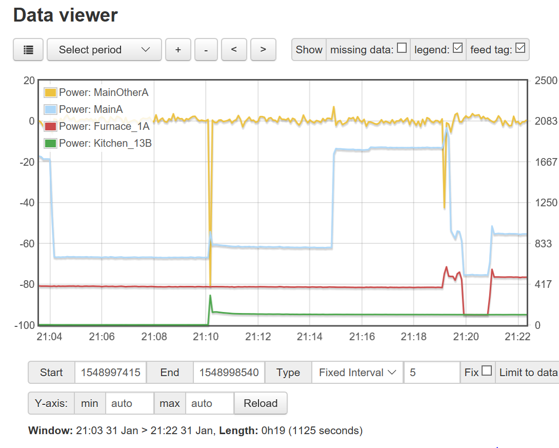
I don’t have an emonpi, but I do have an iotawatt. Here is a picture of some loads and the difference between two CTs that are on the same wire. The main CT is an ECS25200-C2 and the sub-panel CT is an SCT013-000. At just 21:10 the refrigerator turned on, as you can see it has a startup transient. Since the iotawatt does not sample all channels simultaneously, there was a large negative difference between the two CTs on the main line. Similarly at about 12:19 the furnace blower motor turned on. It is a PSC motor with a decent transient draw, so it too caused a difference in the channels to show up
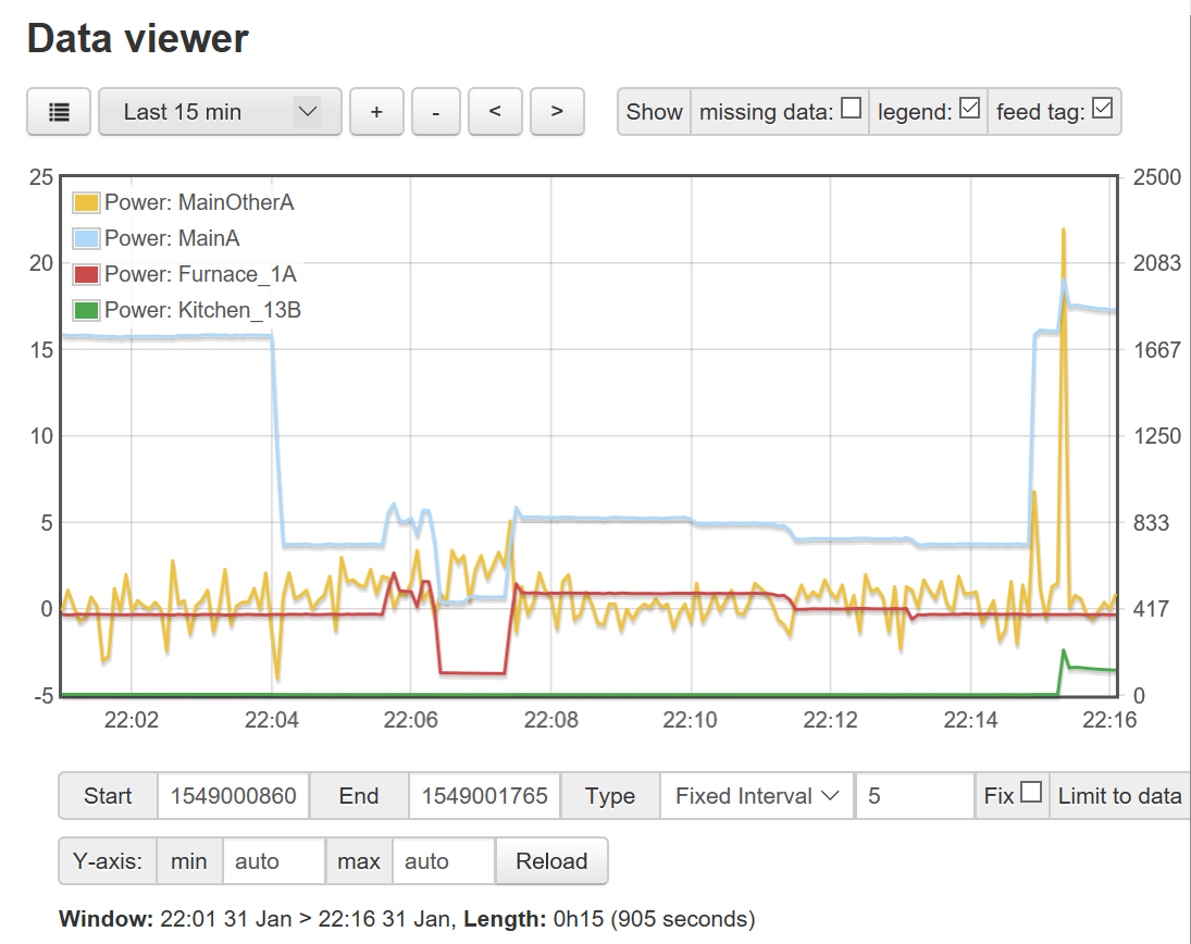
Here is a little later, here you can see the two CTs have general agreement with only a few watts difference. One CT is rated for 200A the other is rated at 100A, but even at the low end with single digit amp loads they generally agree. I’ll bet if they were both ECS25200-C2 they would be even closer. The 1000W increase at 22:15 is the heated floor so completely resistive load and not much of a transient, so the time difference of the sampling does not cause as much difference.
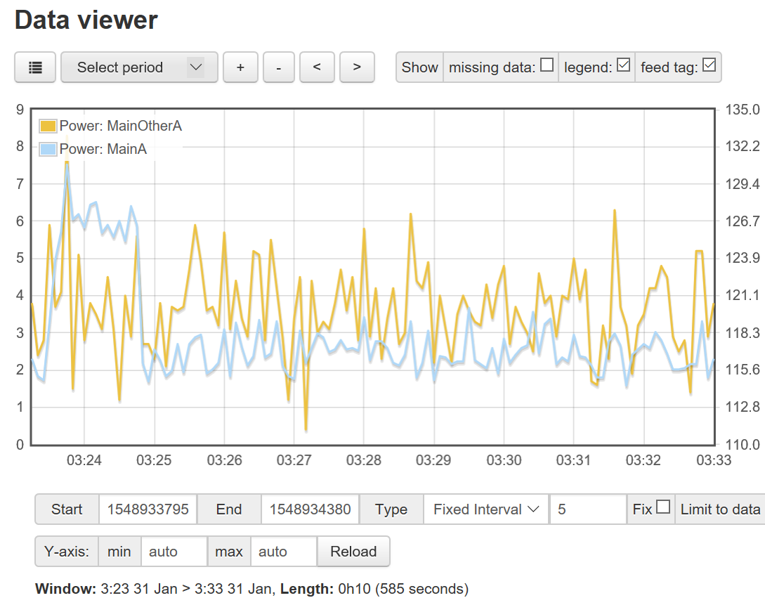
Here we have a time period where there is very low load. I’ll bet that the phase difference between the two is primarily responsible for average difference, but they are still pretty close, considering the load is below 5% of the rated current of the CT of one and 10% of the other. So, it certainly is possible to get good results with relatively inexpensive CTs.
 .
.