First of all, thanks for all the nice Open Source hardware and software.
In order to discover the energy monitoring universe, I have recently bought the following components
1 x emonPi
1 x emonTx V3
2 x emonTH V2
5 x 100A max clip-on current sensor CT
2 x AC-AC Power Supply Adapter - AC voltage sensor (Euro plug)
1 x 5V DC USB Power Adapter (Euro Plug)
2 x RJ45 Encapsulated DS18B20 temperature sensor
Everything is working fine for RF connectivity (emonTX → emonPi and emonTH → emonPi), temperature monitoring (local and remote with emonTH) and single phase CT monitoring.
But I am not able to set up my 3-Phase (french) based energy monitoring with emonTx, even after having crawling the guides and forum. I am a rookie in electronics and electricity, that may be the reason
For the time being, I have
updated the emonTx with the latest 3-Phase firmware
plugged 3 CT into the emonTx “normal” CT inputs and put them on each phase, right after the ouput of my main electric meter.
plugged the AC Voltage sensor on an power outlet connected on one of the 3 phase
Data is now sent by emonTx to emonPi with a “3phase” prefix (it was “emontx3” before the firmware upgrade), with those keys : powerL1, powerL2, powerL3, Vms (and others).
I didn’t proceed with any calibration, and I don’t know right now on which phase my power outlet is connected.
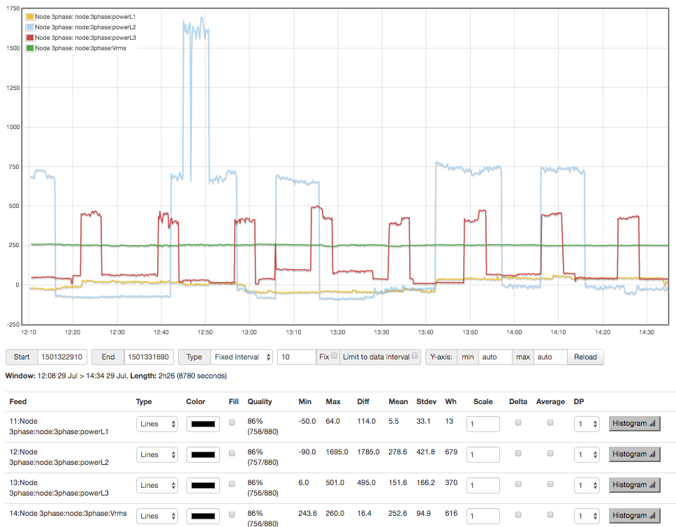
The problem is that I really do not know how to validate my setup, as the values provided by the emonTx seem incomprehensible to me : L1 and L2 are switching from positive to negative values, and L3 is always postive.
Here is the graph of powerL1, powerL2, powerL3 and Vms for a laps of 2h30.
You were looking in the wrong place. The guides generally only talk about the UK single phase system. You need to follow exactly the calibration instructions in the comments at the top of the 3-phase sketch. You are seeing wrong values because you have the three phases mixed up.
The reference is the voltage input, and the 3 ct’s must be on the correct phases in relation to that.
First, you must find which phase the a.c. adapter is on. Everything depends on that. I’ve never done this, but it should work. Ignore CT2 & CT3. Switch off everything in your house. Connect a high-powered electric heater to that outlet as well as the a.c. adapter. Put CT1 on each phase in turn until you read the correct power (approximately - within 10% is OK). That will tell you the phase that the outlet is on. From now on, to the sketch, that is Phase 1.
It does not matter whether that is the brown, black or grey phase at your meter, but the other two ct’s must follow in the correct sequence. To the sketch, these are all the same:
a.c adapter & CT1: brown, CT2: black, CT3: grey
a.c adapter & CT1: black, CT2: grey, CT3: brown
a.c adapter & CT1: grey, CT2: brown, CT3: black.
Now, with only the high-powered electric heater still connected to that phase, do the “calibrate on a single phase only” procedure in the note (in the comments in the sketch). When you have done that, put CT2 onto the next phase in the sequence and CT3 on the last one. Then you should have “sensible” readings on all three phases.
I will follow your instruction to identify phase 1.
The problem is that my 3 phases do not have different colors, they are all black…
Do you know any way to identify the right sequence after the phase 1 ?
About the “calibrate on a single phase only”, I have read the sketch comments, and I have understood that I will first have to put all three CTs on the phase 1, and modify each iCalx values to have the same value read on each CT. Then I must modify Phasecal1 to Phasecal3 to obtain correct power factors and real powers.
But how can I read power factor and real power : Do I have to check the EmonHub monitoring page of EmonCMS (on EmonPi), or is there a way to read it directly through the UART to USB cable connection ?
Moreover, can I update the EmonTx firmware while it have the CTs plugged in and monitoring ?
Unless someone has changed the sketch, you should be able to read the values using a programmer connected to the UART and the Arduino IDE. (If you are using Platformio, I have no idea how to do it with that - I cannot use it because it screwed up my computer system.) You must have #define SERIALPRINT in the sketch (see line 130).
And yes, you can edit and upload the sketch with everything connected.
Is your meter labelled “L1 L2 L3”, or can you Google for a manual for your meter that shows the meter connections? (e.g. Section 6.2 here). Most meters complain if the “phase sequence” is wrong, so I’m guessing that the meter will be correct.
If you cannot do that, then you will have to guess, then test with your heater. If you get the wrong power (50% of what you expect), swap CT2 & CT3. I don’t have a 3-phase supply to test, but that should work.
In my 3 phase meter box, I actually have 3 meters, none of them marked with phase. All my wires are the same colour too (although mine are all red), but I did notice 3 main isolation breakers (which have those lead tied bits of wire sealing them) between the feed-in wires and the meters were labelled in marker pen with ΦA, ΦB & ΦC. I assume these are so the power can be isolated to fix the meters.
I traced the wires from those breakers to the meters and then on to identify which phase the powerpoint with the voltage reference was on and that became phase 1, and then used the other two in order (ABC order) as phases 2 and 3.