NA noob's oobe and questions (starting up the learning curve)

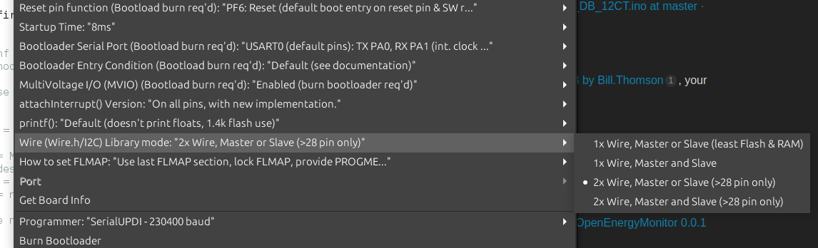
You need to look at the sketch running on the Atmel-DB processor in the front end, and either move the c.t’s around to suit, or maybe modify it to your needs and reload it.

My laptop isn’t serviceable at present, I’ll write more later.

The basic front-end sketch for your emonPi2 is this: GitHub - openenergymonitor/avrdb_firmware: EmonTx4, EmonPi2 & EmonTx5 combined firmware
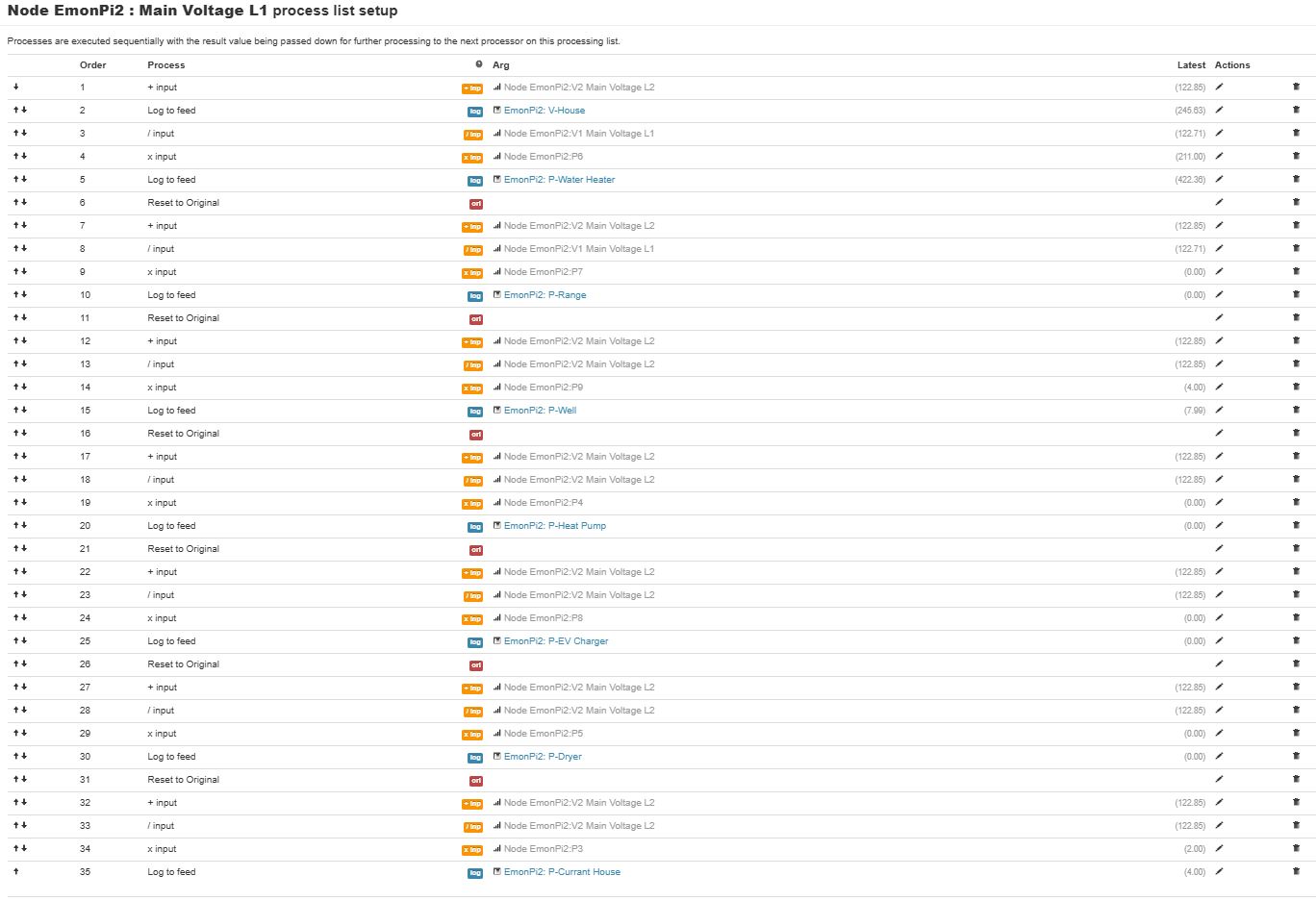
Neither the source nor a compiled version of your specific N.American sketches appear here – I have no idea where @TrystanLea has put them. A proposed list of CT - voltage allocations for the split phase sketch went CT1 - L1: ‘A’ leg, CT2 - L2: ‘B’ leg and so on for all 6 or 12 CT inputs, with all 3 voltages being read, even thought the 3rd is never used. 240 V loads across both legs were not considered.

If you need to read up on emonLibDB, the documentation is is the zip file: EmonLibDB - Version 1.0.2

The front-end sketch comprises two files, you need both. The … .ino file is the main sketch, the … _config.ino handles the serial data in and out to change the configuration. Any changes this can’t handle, and customising the CT - voltage pairing is one, needs to be done by editing, compiling and uploading the sketch to the “emon” board sitting on the RPi extender socket.

If you are intending to make major changes, you might find a simpler starting point is the demo sketches that come with emonLibDB – the max one has an example of every API call, the min one is the absolute minimum to get something sensible to happen, and the rf one sends some data by radio. None of the 3 have either the serial calibration code or values stored in EEPROM - after all, they demonstrate using the library, nothing more.

Probably all you need to change will be block of lines that starts

  EmonLibDB_set_pInput(1, 1);                  // CT1, V1 (etc)
  EmonLibDB_set_pInput(2, 2);
etc.

If it’s acceptable to slow the scan rate to correctly measure your 240 V loads, the commented block of code lower down

/* How to measure Line-Line loads: */

shows you how. (They don’t have to be separate, just add the second voltage to the first block where necessary.)

I’m going to carefully read through what you have written here. In the mean time I am experimenting with “process list setup”

  • Starting with V1, I add V2 and then log this value
  • Using the V1+V2, I multiply by the current of the water heater (P6 / V1) then log this value
  • I do essentially the same for all other 240V circuits: restore V1, add V2 to it, divide that sum by V1 and multiply the resultant by the power, Note that ( (V1+V2)/V1 )*P is the same as (V1+V2) * (P/V1)

Two of the 120V circuits are on the V1 leg so they are just logged
The other 120V circuit requires the P to be divide by V1 then multiplied by V2

Here’s the screen capture:

This looks like it’2 working:

I suggest you look at the ‘Learn’ part of Docs and read up on how we calculate power. It would appear, from what you’ve written, you don’t understand the most fundamental facts of digitally measuring power.

You write

No, generally it isn’t. It is that only in one very particular circumstance - both voltage and current are pure sine waves. In real life, voltage might be close, current is far less likely to be.

Next, you need to explain why you’re doing this:

Why do you need to do this? By correctly linking the c.t. with the voltage - and as I explained above this has already been done for you, you get the power already calculated on the Inputs page of emonCMS. There is absolutely no reason to do what you appear to have in that screenshot - it looks to be completely unnecessary.

What I would expect to do is, start with the hardware. First, prove that CT1 is linked in the front-end sketch to V1 - the L1 voltage. Disconnect your live feed to L2 - if the odd numbered powers and energies (P1, E1; P3, E3 and so on) continue to show credible values and the even numbered ones collapse to zero (or in the case E2, E4 etc - remain static), then my assumption about the linking between CTs and voltages is correct. If this doesn’t happen, then you can either move the hardware around or re-program the front end to suit how you’ve installed the c.t’s.

Having done that, in the process list (emonCMS → Inputs →behind the spanner icon) for each Power Pn is where you log the power to a Feed (the database) and do whatever else you need. Maybe you want the total power for a group of circuits? Do that in the lowest one down the Inputs page (because by the time that is processed, emonCMS has all the ones above that have been recorded at the same instant. If you use an input below, the value could be 10 s old).

The calculation of power from voltage and current has already been done for you, you do NOT need to multiply a current (where did you get it from - it’s not normally sent to emonHub and to emonCMS?) and even if you did, you’d get apparent power, not real (active) power which is what you pay for.

1 Like

Ah, yes, I forgot the beauty of emonPi2.

Let’s see if I have this right. Voltage (V) and Amperage (A), are sampled every sample-period (Ts). Multiplying these three together is an approximation the energy during Ts in Joules (J). In any period (T), the square root of the average of the sum of the squares of J will result in the energy during T, which I call Jt. Divide Jt by T to get power (P). The smaller the sample-period and/or the more samples, the more accurate the reading.

Something like that.

The bottom line is to pair (aka link) the CT with the Voltage, not to manipulate the resultant values.

In the USA, it is easy to visually inspect the panel to know the physical relationship between V1 and V2 and the CTs. From your description, what happens between the utility transformer and where the wires start their way to the outlet are very different in our two locations.

I’m not seeing where one can do this pair(linking). I assume this is found in How to compile and upload firmware This process is daunting!

Since I am familiar with the Arduino IDE, I take the " Compile and Upload using Arduino IDE". I follow this carefully!

I deviate slightly at “Open the base firmware that you wish to use in the Arduino IDE” and I select the emon_DB_12CT.ino. At “Change any other compile options as required” I change NUM_V_CHANNELS to 3 and uncomment #define ENABLE_ENERGY

End of page, I assume it’s time to compile. … No joy :frowning:

C:\Users\uname\Documents\Arduino\emon_DB_12CT_v1\emon_DB_12CT_v1.ino: In function 'void setup()':
C:\Users\uname\Documents\Arduino\emon_DB_12CT_v1\emon_DB_12CT_v1.ino:175:3: error: 'Wire1' was not declared in this scope
   Wire1.swap(2);
   ^~~~~
C:\Users\uname\Documents\Arduino\emon_DB_12CT_v1\emon_DB_12CT_v1.ino:175:3: note: suggested alternative: 'Wire'
   Wire1.swap(2);
   ^~~~~
   Wire
exit status 1

Compilation error: 'Wire1' was not declared in this scope

Am I on the right track? What is this error?

Of course, thank for all your help. I plan to create a document of going from 0 to monitoring data in the USA. This is why I am trying to document everything.

You’ve fallen at the first hurdle. rms energy has absolutely no meaning, physically. Neither for that matter, in case you were thinking otherwise, has rms power. There’s total energy, and plain average power; over the same period, they are very closely related.

Correct.

This is where the problem lies. I believe The Shop will customise the “emonPi2 DB N.American…” sketch provided in your emonPi2 according to your requirements if you ask at order time. Otherwise, they will send it out with the default pairing I outlined earlier. Unfortunately, I haven’t seen anything relating to this published anywhere.
There’s no reason in principle why the pairing cannot be done with the serial interface from a page that is part of the emonCMS configuration (Admin → Serial Config), but there are practical limitations: my immediate thought is the settings need to be retained in EEPROM, which means there’s less room for the energy values - these are rotated for wear levelling and it means the EEPROM stands to wear out sooner - and it’s on-chip so cannot be replaced. But it need cost only 6 bytes in total, it’s not onerous. This might be the only reason, or it might be that Trystan didn’t envisage a need when he wrote the sketch in the Atmel-DB processor, which is where the settings that need to be changed reside. Yes, the process is somewhat complicated, but once you’ve done it a few times (and got a BASH script to push the files across) it’s fairly straightforward. The good news is it’s a very simple change to the API calls.

Yes. You must go through all the #define lines to check which you need.
One caution: be absolutely sure you keep your changes somewhere safe and not on the SD card in the Pi, because they won’t be part of the SD download and will be lost when your SD card wears out.

You’re missing (probably) the Wire1 library. I don’t have an emonPi2 so I’ve never been there.
It’s not listed in Installing the Arduino Libraries – Ubuntu Linux — OpenEnergyMonitor 0.0.1 documentation nor in Firmware — OpenEnergyMonitor 0.0.1 documentation so this is a question for @TrystanLea - those pages (for all OSs) need updating.
And don’t ask me about platfromio, I refuse to use it. When I tried it, it moved my files around - didn’t make symlinks - and screwed up the rest of my system: malware in my book, and it hit the bit-bucket pretty fast as soon as I discovered what it had done.
I can help with the Arduino IDE, if you need me.

Hello @Grape

Apologies for the slow reply on this.

This is the firmware we use for North American 12CT configuration:
avrdb_firmware/emon_DB_12CT/emon_DB_12CT.ino at master · openenergymonitor/avrdb_firmware · GitHub

Number of voltage channels is set to 3 (even though we only use 2):

#define NUM_V_CHANNELS 3

Then the voltage channel allocation is, 1,2.. alternate

#if NUM_V_CHANNELS == 3
  EmonLibDB_set_pInput(1, 1);                  // CT1, V1 (etc)
  EmonLibDB_set_pInput(2, 2);
  EmonLibDB_set_pInput(3, 1);
  EmonLibDB_set_pInput(4, 2);  
  EmonLibDB_set_pInput(5, 1);
  EmonLibDB_set_pInput(6, 2);
  EmonLibDB_set_pInput(7, 1);                  // CT7, V1 (etc)  
  EmonLibDB_set_pInput(8, 2);
  EmonLibDB_set_pInput(9, 1);
  EmonLibDB_set_pInput(10, 2);  
  EmonLibDB_set_pInput(11, 1);
  EmonLibDB_set_pInput(12, 2);

USA is also set to true here: avrdb_firmware/emon_DB_12CT/emon_DB_12CT.ino at master · openenergymonitor/avrdb_firmware · GitHub

and apologies I thought I did have this written somewhere!

There’s a thread over at emonTx V4, emonVS in North America - #73 by Bill.Thomson, your probably familiar with this already.

The one wire library is noted in the firmware docs here: Firmware — OpenEnergyMonitor 0.0.1 documentation

  1. Download DxCore SpenceKonde OneWire library:

@Grape did you get this one installed?

The same thing? Now that’s downright misleading, giving the class a ‘reversed’ name.

Thinking about it, it would do no harm to mention Spence Konde in the original Arduino library list too - it wasn’t needed when I first wrote those pages.

Now I did a double take, maybe it’s not the library and it’s this Arduino IDE setting that enables Wire1:

I just added this above.

1 Like

I just made the change and now it seems to compile.

But!

I get this output when I compile:

c:\Users\uname\Documents\Arduino\libraries\RFM69_LPL\RFM69_LPL.cpp:169:110: warning: default argument given for parameter 4 of 'void RFM69::send_csma(uint16_t, const void*, uint8_t, uint8_t)' [-fpermissive]
 void RFM69::send_csma(uint16_t toAddress, const void* buffer, uint8_t bufferSize, uint8_t custom_csma_limit=0)
                                                                                                              ^
In file included from c:\Users\uname\Documents\Arduino\libraries\RFM69_LPL\RFM69_LPL.cpp:26:0:
c:\Users\uname\Documents\Arduino\libraries\RFM69_LPL\RFM69_LPL.h:71:10: note: previous specification in 'void RFM69::send_csma(uint16_t, const void*, uint8_t, uint8_t)' here
     void send_csma(uint16_t toAddress, const void* buffer, uint8_t bufferSize, uint8_t custom_csma_limit=0);
          ^~~~~~~~~
Sketch uses 33754 bytes (25%) of program storage space. Maximum is 130560 bytes.
Global variables use 8665 bytes (52%) of dynamic memory, leaving 7719 bytes for local variables. Maximum is 16384 bytes.

When I compile the second time, the message doesn’t appear! ???

Now I have a binary file. Can you provide me with the link with the instructions the guide me how to upload it to my emonPi2?

I do appreciate this help and I am much looking forward to getting this working!

I have another thought which I’ll put into a subsequent post.

Those warnings can be ignored. Are you using the Arduino IDE? if so you just click Upload and it does compile and upload all in one..

OK, in the default NA 12CT configuration, the odd numbered CT’s associate with the L1 and the even’s with L2.

This would all be well and good except that this is not the situation for every panel I’ve every opened. There are two confounding realities we face here in the USA. Sadly, electricians, or the developers that hire and direct electricians, value the bottom line as “Job 1” and good work does not seem to be on the list of priorities. Secondly, hacks like me, add spurious circuits to the panel in random places (eg. EV chargers, backup generators, something my wife wants, etc.) There are exceptions.

That said, I may be able to reconfigure my CTs and/or breakers to conform to these settings. I’ll have to assume that, because of my order, the calibration set at The Shop for my CTs is:
1:200A
2:200A
3:100A
4:50A
5:50A
6:50A
7:50A
8:50A
9:20A
10:20A
11:20A
12:20A
Is that a good assumption?

I connect a USB cable from my computer to the USB of the emonPi2? (not the USB of the Raspberry Pi Zero 2W inside the box) That would be too easy! :slight_smile:

1 Like

I am glad you are working on this! I have been plugging along with it in NA as well. As long as you are updating the firmware, my thought would be that you configure the firmware to match each CT to the leg the measured circuit is using, rather than trying to choose the CTs to match the firmware’s expectations. See this part of the NA topic: emonTx V4, emonVS in North America - #26 by Robert.Wall

Can I ask how you connected your emonVS to your breaker panel?

1 Like

That would be my expectation too, except that the linkage between voltage and current is hard-coded into the front-end sketch, and requires a recompile and upload, which makes it a lot harder for many users. Angus tells me this problem disappears with the emonPi3 & emonTx6.

Aha of course you have the pi connected, good question, yes you can do it that way, I usually remove the SD card so that the Pi is not trying to do things (power down power back up first). Or alternatively you can use the binary that you have generated and use the Admin > Update > Firmware upload tool, see: Local emoncms custom firmware upload option

Agreed, the intention was just to provide a starting point with custom configuration via firmware modification required to tailor for specific installations. In general we’ve managed to remove the need for firmware configuration but this is one where unfortunately this more advanced level configuration is still required.

Sure.

I had two neighboring unused locations in my panel. I also had two 20A breakers. (Yes, 20A is not going to protect the emonVs, but not any less than plugging into a 240V outlet connected to 20A breakers. Ground (earth) (green or bare copper) and neutral (white) go to their appropriate bus. (Local regulations for this vary widely.)

All the panels I’ve encountered in NA alternate L1 and L2. This is allows for neighboring breakers to be joined to form a 240V circuit. I arbitrarily assigned one of my feeds from the utility L1. By looking at where the breaker connects to the bus, one can ascertain to which of L1 or L2 the breaker (circuit) is connected.

I put a clip across the the two emon breakers so they both trip if one trips.

Fearing that I might brick the emonPi2, I decided to move CTs and a breaker. This seems to be working, except that a I have at least two circuits reporting negative power. I checked to see if all of the CTs were installed with the L of the CT on the load side of the wire. Of course I will reconfirm, but in the mean time, is there another explanation?

I have a CT each of the incoming feeds to the panel. What is the optimal way to determine the whole house power? Is this done in the library or do I add the P1 and P2 together?