NA noob's oobe and questions (starting up the learning curve)

I have one question so far, which I have highlighted with bold font.

I just received my hardware. This is called oobe, Out of Box Experience. And I am relatively new to Open Energy, so I’m a noob (word derived from new and boobie, meaning someone who seeks to learn something new and needs help.)

And I’m in North America (NA) where we do things a little differently and have different names. Not better or worse, just different. Fortunately, the fundamentals of electric energy are universal.

The first thing was to check that all the items on the invoice are the same as those in the box: emonPi2, emonVS(USA), 12 CTs. I couldn’t find the expansion board and realized it was already installed in the emonPi2 enclosure.

I don’t like blowing things up. Just yesterday I was installing a single phase switch/outlet and I made assumptions that were wrong (black to black and white to white, right? not on this switch). I don’t want to do that on something that cost $500! So I start at the emon2Pi Install Guide

The Quick Start assumes that the emonVS is already connected. It’s not. I jump down to 1. emonVs installation.

In NA a residential house has a split phase L1 measured from the neutral is 120VAC. L2, the other phase also measures 120VAC but is 180° out of phase with L1. Thus, the Voltage from L1 to L2 is 240VAC. Protection devices are almost always breakers (circuit breaker with can protect multiple times as opposed to fuse which is one time). I believe what you call a fuse board is called a panel in NA.

“suitably competent person”: I have an advanced degree in Electrical Engineering, I worked for an electrical utility company as an engineer and I have wired three houses. I even designed and built a still employed low cost energy meter. emon is far superior. I am also competent in software, too, having taught computer science (and electronics) at the university level and designed and built industrial automation equipment.

In the emonVs there is a connector [L3 L2 L1 N E] I make the obvious assumption about what connects to L2, L1, and N

E, I assume means earth ground which is connected to the earth. In NA, we pound a 2m copper clad iron rod into the ground, leaving a bit above to which we attach a brass lug which connects a bare copper wire which is fed up in to the panel and connected to a bus bar. In NA this is ground. I have to ask the following question because, often, in NA, the neutral bus bar and the ground bus bar are one in the same.

Should E be connected to NA ground?

Continuing on in 1. is see that I will "use the split phase firmware
". Following the link, I find “A custom phase allocation will likely be required for this configuration which can be achieved by minor firmware modification.”

Considering my order, NA, emonPi2, emonVS, expansion board and 12 current transformers, is the ID 3 emonPi2_DB_12CT_1phase with the firmware modification pre-installed? Is there a way to query the emonPi2 to determine this?

To answer these questions, I need to have the emonPi2 running. I do that by connecting a “death cord” (lamp cord with [keyed] plug and bare wires :open_mouth: ) to L1 and N (smooth side to L1 and ribbed side to N) of the emonVs, connecting the 8 conductor cable between the emonVs and emonPi2, then plugging into an outlet. Cool, it came up!

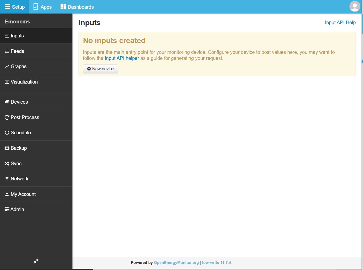
Next is to connect to the emonPi2 web page. This is 6. on the getting started page. Unfortunately, my computer (Windows 10) won’t allow me to enter more than 8 characters in the passphrase of the WiFi. My phone did. With a bit of bumbling, I connected the emonPi2 to my WiFi network. Pressing the button on the emonPi2 several times allowed me to see the IP address of the emonPi2. I logged in with user and password of emonsd.

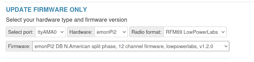
After the detour of connecting the WiFi, these questions are answered on the Firmware page by Updating firmware. Under UPDATE FIRMWARE ONLY, in the Firmware dropdown box I discover emonPi2 DB N.American split phase, 12 channel firmware, lowpowerlabs, v1.20. With trepidation, I click on [UpdateFirmware]. No untoward messages and ending with SUCCESS and restarting. I was unable to find a description of the emonPi2 firmware on the emonPi2 web page.

Whew!

Step 2. CT sensors installation. This is straight forward, but takes some planning and real care because I’ll be in the panel with live 240VAC with 200A available. To avoid miswiring, I’ll label both ends of each CT first.

It appears that it does not matter if the CT calibration is done later. I’d feel more comfortable if I did that before the CTs are on the wires.

I’ll continue with a reply to this topic.

Yes.

And you might like to look at the page in Docs about the differences between North American and British electrical systems.

This should help you translate your terminology to real English and vice versa. :wink:

In the UK, your panel is a Consumer Unit. All modern installations will use breakers too.
Some examples: https://www.screwfix.com/c/electrical-lighting/consumer-units/cat7230028

Correct - they are voltage output c.t’s, so all calibration does is change the multiplier in software. But of course, the c.t. will saturate if you pass more than the rated current through it, and calibration won’t help there.

That wouldn’t worry me. On a UK 3-phase installation, we have 240 V to earth (ground to you) and 415 V line–line. But of course you must know what you’re doing when working on live parts, and watch out for things that haven’t been done correctly in the past - or not upgraded to comply with present practice and standards. And the fault level on your supply is probably quite a bit lower than it is on mine – and that’s what I’m really wary about, mine’s about 400 kVA.

Ooh, big mistake. That’s what I mean about watching out for things that haven’t been done right in the past.
(And I’m really writing this as warning others who read this later, not trying to tell you.)

One of my moderator colleagues is in Oklahoma, so he’ll probably be able to help you with anything peculiar to North American practice. And your background sounds very similar to mine - except I’ve always done it, never taught it - until I came here.

1 Like

Ok! all the hardware, including CTs, is installed, the emonPi2 turns on and I can log into the emonCMS of the emonPi2. The next step is to ensure that the CTs are configured correctly in the emonPi2.

7. EmonCMS setup which has me go to the emonCMS: Getting started emonPi/Base
page. I get to step 3. Inputs page. My page doesn’t look like that. :frowning:

I remember that I upgraded my firmware to emonPi2 DB N.American split phase, 12 channel firmware, lowpowerlabs, v1.20 I start to thrash. here is Admin–>System Info:

Server Information

Server Information

Services

  • service-runner :- Activating loaded activating auto-restart

  • emoncms_sync :- Activating loaded activating auto-restart

  • emoncms_mqtt :- Active Running

  • feedwriter :- Active Running - sleep 300s 0 feed points pending write

  • redis-server :- Active Running

  • mosquitto :- Active Running

  • emonhub :- Not found or not installed

  • emonPiLCD :- Not found or not installed

  • demandshaper :- Not found or not installed

Emoncms

Server

  • Machine :- Oracle Corporation VirtualBox/VirtualBox, BIOS VirtualBox 12/01/2006
  • CPU :- Intel(R) Core™ i5-4590 CPU @ 3.30GHz | 1 Threads(s) | 2 Core(s) | 1 Sockets(s) | 6578.52MIPS |
  • OS :- Linux 6.8.0-63-generic
  • Host :- emon | emon | (192.168.0.197)
  • Date :- 2025-07-12 02:34:11 UTC
  • Uptime :- 02:34:11 up 5 days, 11:33, 0 user, load average: 0.02, 0.01, 0.00

Memory

  • RAM :- Used: 19.43%
    • Total :- 1.92 GB
    • Used :- 382.41 MB
    • Free :- 1.55 GB
  • Swap :- Used: 0.00%
    • Total :- 2 GB
    • Used :- 0 B
    • Free :- 2 GB

Disk

  • **** :- - / :- Used: 22.78%
    • Total :- 24.44 GB
    • Used :- 5.57 GB
    • Free :- 17.6 GB
    • Read Load :- 363.29 B/s
    • Write Load :- 17.77 KB/s
    • Load Time :- 1 days 10 hours 30 mins

HTTP

  • Server :- Apache/2.4.58 (Ubuntu) HTTP/1.1 CGI/1.1 80

MySQL

  • Version :- 10.11.13-MariaDB-0ubuntu0.24.04.1
  • Host :- 127.0.0.1 (127.0.0.1)
  • Date :- 2025-07-12 02:34:11 (UTC 00:00‌​)
  • Stats :- Uptime: 473590 Threads: 6 Questions: 33842 Slow queries: 0 Opens: 48 Open tables: 41 Queries per second avg: 0.071

Redis

  • Version :-
    • Redis Server :- 7.0.15
    • PHP Redis :- 6.2.0
  • Host :- localhost:6379
  • Size :- 5 keys (1.14M)
  • Uptime :- 5 days

MQTT Server

  • Version :- Mosquitto 2.0.18
  • Host :- localhost:1883 (127.0.0.1)

PHP

  • Version :- 8.3.6 (Zend Version 4.3.6)
  • Run user :- User: www-data Group: www-data Script Owner: grape
  • Modules :- apache2handler calendar Core ctype curl date dom v20031129exif FFI fileinfo filter ftp gd gettext hash iconv json libxml mbstring mosquitto v0.4.0mysqli mysqlnd vmysqlnd 8.3.6openssl pcre PDO pdo_mysql Phar posix random readline redis v6.2.0Reflection session shmop SimpleXML sockets sodium SPL standard sysvmsg sysvsem sysvshm tokenizer xml xmlreader xmlwriter xsl Zend OPcache zlib
Client Information

Client Information

HTTP

  • Browser :- Mozilla/5.0 (Windows NT 10.0; Win64; x64) AppleWebKit/537.36 (KHTML, like Gecko) Chrome/138.0.0.0 Safari/537.36
  • Language :- en-US,en;q=0.9

Window

  • Size :- 1183 x 892

Screen

  • Resolution :- 2752 x 1152
In my thrashing I cannot open a terminal window (Admin-->Serial Monitor), I only have tty's S0-S4 and I cannot SSH into the machine because username and/or password not accepted. (I tried my emonCMS U/P and various combinations of the default and many other combinations.)

The pushbutton on the emonPi2 is acting as expected. (that’s how I enabled ssh)

I hope there is someone that can help me. In the meantime, I’ll reload the firmware.

Update didn’t work either /var/log/emoncms/update.log does not exist

Now I have to figure out how to put an image on a microSD card. :frowning:

Updating the easiest way didn’t work because I have no ttyAMA0

Upload pre-compiled didn’t work because I have no command line. Likewise for Upload pre-compiled manually using avrdude

I tried How to compile and upload firmware because I have familiarity with the Arduino IDE. A lot of install apps, copy and paste, etc. I got to the point where I’m suppose to be able to compile and download (upload?).

In the first compile attempt I get an error message about a missing library, SSD1306Ascii.h which appears to be the text for the display, which a quick search found and I installed with the rest of the Arduino libraries.

The next compile got this:

C:\Users\uname\Documents\Arduino\__x\avrdb_firmware\emon_DB_12CT\emon_DB_12CT.ino: In function 'void setup()':
C:\Users\uname\Documents\Arduino\__x\avrdb_firmware\emon_DB_12CT\emon_DB_12CT.ino:175:3: error: 'Wire1' was not declared in this scope
   Wire1.swap(2);
   ^~~~~
C:\Users\uname\Documents\Arduino\__x\avrdb_firmware\emon_DB_12CT\emon_DB_12CT.ino:175:3: note: suggested alternative: 'Wire'
   Wire1.swap(2);
   ^~~~~
   Wire
exit status 1

Compilation error: 'Wire1' was not declared in this scope

:frowning:

Is there not an ISO which I can put on an SD card with Rufus or Balena Etcher?

I don’t have an emoni2, so I can’t even begin to try to replicate what you’ve done fiddling about.

I think I agree with you and your best course of action is to start again. Try searching the Docs section for “SD Download” and get the latest (the top one on the list) which is emonSD-01Feb24.

When you’ve put it onto the SD card and made the file to enable SSH, and before you put the SD card into your Pi, you might also want to create/edit the file with your WiFi credentials in so that it will connect straight away.
On the SD Card, find the file "/etc/wpa_supplicant/wpa_supplicant.conf " (it might be somewhere else :roll_eyes:) and open it with a text editor. Change it so that it reads something like mine (below), obviously putting your details to replace the square brackets and what’s inside them.

ctrl_interface=DIR=/var/run/wpa_supplicant GROUP=netdev
update_config=1
country=[GB]

network={
        ssid=[Your SSID]
        psk=[Your Wi-Fi password]
}

N.B.
The official RPi info says this - but my file doesn’t have the two extra lines.

country=US
ctrl_interface=DIR=/var/run/wpa_supplicant GROUP=netdev
update_config=1
network={
 ssid="YOURSSID"
 scan_ssid=1
 psk="YOURPASSWORD"
 key_mgmt=WPA-PSK
}

(And pre-empting your question, I don’t know why this has been removed from the Docs, it used to be in there.)

Power it up, connect to your Internet and wait a long time while it updates itself.
After it’s completed, you should be back to where you can register your account in emonCMS.

Now update your front-end sketch (the “emon” part, not the RPi) using the Admin → Update page

Your Inputs page should get populated with 12 Inputs for your 12 CT channels, plus voltages, etc. If it doesn’t, ASK, don’t fiddle and mess things up again.

I had just found the download page and had started the imaging process using the RPi imager (and a different SD card), which, in theory, allows you to set ssh to enable and supply the WiFi credentials. Now I’m at the

part of the process and decided to look at my email and found your message.

I am using Window 10. The second partition of the SD card is not readable from Windows. Is it ext4? When you suggest to enable ssh and WiFi I assume that those files to modify are in that file system. I do have linux systems but I need to get an SD card reader.

I had a good chuckle with:

It is my nature to fiddle. Fortunately, I have the resources and patience to take responsibility for my fiddling. The first thing I did when I got my first digital pocket watch (in 1976) was to take it apart. I think I still have it and I’m pretty sure it still works. It literally preserved my life because it was accurate to +/- 4 sec/year.

Still “emonPi2 starting”

The second partition is the EXT4 one, but the files to setup SSH etc are in the FAT partition, so you don’t need a Linux box handy :slight_smile:

It’s been 2 hours with the display at
emonPi2
starting..
Is that more than wait a long time?

II would say so.

Search for a post about RPi Imager - it’s caused some people problems in the past. I’ve always used Balena Etcher - but then I run Ubuntu Linux. I can’t say if or how it works with Windows (I gave up on that with Win8).

I’m back on track!

I created the SD card using Balen Etcher (had to unzip the download first). I couldn’t find the configuration files mentioned. No worries, I connected to the emonAP and set it up. Also enabled ssh from the display and it’s working. The download page indicates putting a file /boot/ssh into the FAT partition will enable ssh … it didn’t.

I tried a number of things. One was to use a 32GB microSDcard. What worked was to overwrite the supplied 16GB microSDcard and suppress my curiosity, following each step without deviating. That only did get the inputs to populate, though it appears that I must have at least 1 CT plugged in.

Onward to the next layer of the onion.

1 Like

No you didn’t. Etcher accepts either. From the Forum Discussion thread linked from the Docs entry for Etcher:

I wrote that because when I went to select the image, the filter didn’t show zip files.

I continue my journey at 8. CT calibration selection. This did not go well at all.

I went to setup–>admin–>serial config. The first thing I notice was that there were only 6 CTs shown. In the black window below the settings for the 6 CTs, but not the other 6. Near the top was note showing the firmware, which indicated the 12 CT firmware.

Next I stopped the emonHub and started the serial config. I decided to change one of the CTs, to get experience doing that. I clicked on [Save], then [Stop Serial] and [Start Hub]. After that, the webpage was unresponsive.

At the emonPi2 I did a manual shutdown, waited the 30 seconds and power cycled the unit.

Going back to the Serial Config page, in the black window I see many
MSG:83,V1:122.46,V2:122.67,V3:0.00,F:59.94,P1:-3559,P2:3572,P3:3,P4:1,P5:0,P6:10,P7:-3,P8:-3325,P9:-3,P10:1,P11:0,P12:5
and the CTs are set to 20A.

I try to change this [Stop hub], set serial, [start]. This time sending an ‘l’ from the console gets no response. I click on [Stop serial] but get no feedback that anything happened. In a few moments, the page says “Site cannot be reached”. Unresponsive to ping.

After a power cycle, my ssh password is “incorrect”

I’ve tried subtle variations to no avail. Here is the message I get when just before things go south

Any thoughts?

Another data point.

After some experimentation, I found that the WiFi connection was being dropped when, in Serial Config, I saved a changed setting and clicked on [Stop Serial].

If I enabled the AP (button on emonPi2), I could connect to the emonPi2, Then click on [Stop Serial]

Even though my computer was less than a meter from the emonPi2, even with an AP connection, the WiFi would drop.

There’s something amiss around stopping emonHub and starting the Serial Monitor. I don’t have an emonPi2, but I’ve been playing around with an emonPi1 and things aren’t happening as I think they should. Whether this is a constraint of the serial data flow into the front end sketch, similar to turning on the serial monitor in the Arduino IDE invariably causes a reset, a deliberate action or an oversight deep in the code somewhere - I don’t know.

What appears to be happening is “Stop enonHub” doesn’t stop data arriving (which is what you might be expecting) and data continues to be sent from the front end. Setting the datalog period temporarily to 30 s or more [send the command d30] gives you time to send commands between data arriving from the front end (Node 5). Remember to set it back to 9.8 s before you finish.
Stopping emonHub then starting Serial Monitor appears to restart the front end, sending “Pi is booting - Please wait” to the display, which gives the impression the Pi has rebooted. I don’t think is has, because seconds later, it thinks it’s been up for many days.

Mine hasn’t appeared to have dropped the Wi-Fi connection.

I don’t have an SSH password, I use a key file pair with no password on the private key, meaning my laptop is the authorised user, not me. That mechanism has never been corrupted.

I’ve never got Serial Config Tool to work any differently to Serial Monitor, all it produces is “Firmware update required:…” despite having updated the OS, emonCMS and separately the front end sketch (is this what “Firmware” means?) minutes previously.

While Serial Config does not seem to be working, I think my emonPi2 is configured properly. So for now I’m going to ignore that (?)bug.

I had to suspect that my network loss problem was and insufficient WiFi signal. I moved my WiFi access point closer to the emonPi2 (couldn’t very well move the whole panel :wink: ) So far I haven’t seen any WiFi drops.

I do have an installation question. In Use in North America is Note that CT 1 faces to the right and CT 2 faces to the left I have installed my two 200A panel feed this way. Is this correct? Reading further I see this as a NO You should set up two power channels, one using CT1 and V1 and the second using CT2 and V2, and add the resulting powers to give the total. I noticed that one of my other CTs is backwards which means I have to go back in the panel again (grrrrrr).

With this understanding, for 240V loads, I sum V1 and V2 and multiply by the CT on that circuit. For 120V loads, I’ll need to know to which phase the circuit is connected and use the V of that phase (times the CT). Right?

In the NA split phase, V1 is from neutral to the phase, and V2 is to the other phase. Is V3=V1+V2 or is V3 just not used?

I have some serious studying to do to determine what I want to monitor, how to monitor it, and how to present the data.

Thanks for all your help

What do you mean, phase? You have a split supply, it’s all one phase off one winding of the transformer.

Part 1 was written long before the emonVs, the emonTx4/5 and the emonPi2 appeared. Did you read as far as Part 2?

You don’t do the multiplying.
For 120 V loads, you must correctly pair up the c.t. with the correct voltage. emonLibDB will do the multiplication.
For 240 V loads, you can tell it both voltages and emonLibDB will do the maths correctly for you, whether the voltages are two legs of the same phase, or different phases. See the documentation. As far as I know, The Shop hasn’t made a sketch available to take advantage of this. It does take longer to do the calculations, so of necessity it slows the sample rate somewhat.
Here’s what the emonLibDB documentation says:

void EmonLibDB_set_pInput(uint8_t _cInput, uint8_t _vInput1 [, uint8_t _vInput2])
Sets the relationship between voltage and current inputs to enable the calculation of real
power. For single-phase, one leg of a split-phase and 3-phase 4-wire measurements,
voltage and current sensor must be on the same phase/leg. The second voltage is needed
only for the line-line power calculation in split-phase and 3-phase systems; i.e. when the
current measured is line-line.

V3 will be the voltage measured between the L3 and N terminals on your emonVs. You might pick up the odd volt or two from stray capacitance, but in the ideal world, it will be zero. Remember, your supply system is the odd one out, the rest of the world does it roughly like we do.

Or put `scales = [a negative number] for that c.t. in emonhub.conf, or a ×(-1) in the maths in the input processing? (But turning the c.t. around will avoid confusion when you’ve forgotten why there’s minus there.)

Phase … that always bothered me, too. Here in the USA it commonly refers to the different legs, L1 and L2.

Yeah, it’s better to go back into the panel and do it right. It can be dangerous if one does. For example, in the USA, the black wire is line and the white is neutral. In 240V circuits, the the other line is red. My experience is that if one is using 2 wire (plus ground) romex for a 240V circuit, the white wire should have red tape on it to indicate that it is L2. I just encountered two places where it was not! Bad to confuse a line with neutral!

OK, all good (for) now. Onward!

My goal is to have a graph of whole house kW.

I gather the description of the inputs from here but that leaves out Vn, F (which are obvious) and, “1”, which is not intuitive. (breaking out in song … is the loneliest number …)

I’m not understanding Pn (where n is 1-12). P = V * I * φ. I is the current going through the CT, φ, the phase angle between V and I, but what is the source of V? I have V1, V2 and V1+V2. I have 120V circuits, which could be sourced from either leg, and 240V circuits.

P1 and P2 are on the main feed cables, and seem to be associated with V1 and V2 respectively (because the powers are positive and almost the same). Seven other circuits are 240V; on six of these the CTs are on the V1 feed, the other on the V2 feed. Theses need to use V1+V2. The remaining are on 120V circuits, two on V1 and one V2. This latter P is negative.

Is this how it’s done?
**


How do I specify with which V to associate the P?**