Here’s the schematic of my system for comparison:
- Like Nick I’ve got multiple emitter circuits, each with their own zone valve and pump
- I can control these independently via relays on the Home Automation system
- In practice they all run 24x7 from October through March and the heat pump’s Weather Compensation logic adjusts the temperature of the water to control the heat output
- Like Nick I’ve got a Buffer Tank but mine is plumbed ‘in series’ to add water volume to the Flow circuit and guard against short-cycling of the heat pump
- There’s a Charge Pump inside the GSHP unit which circulates water from Flow to Return
- I’ve just realised the sketch is slightly wrong; there’s only one pump, upstream of the diverter valve
- Unlike Nick I’ve got a Low Loss Header which provides ‘hydraulic separation’ between the multiple pumped Emitter circuits
- It doesn’t matter how many of the Emitter circuits are calling for heat, there’s no tendency for e.g. the UFH pump to affect the flow of water through the heat pump
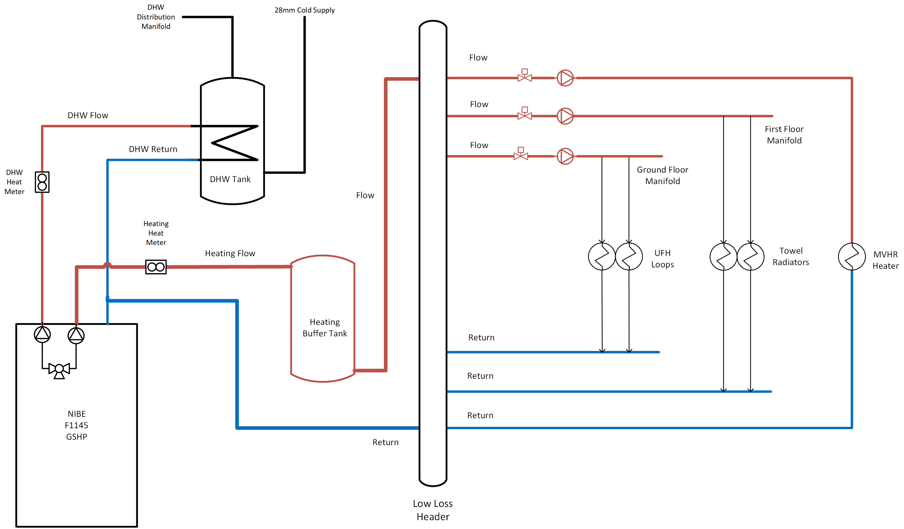
I should add that this is very firmly Not To Scale! The Low Loss Header is nothing like that big in reality.
Also worth noting that I contracted one company to install the heat pump and its ancillaries whereas my builder used a different company to do the heat emitter circuits along with the rest of the plumbing in my self-build, so I had to make it clear who was quoting for which aspects. This schematic dates from that time, where we agreed the builder was responsible for the LLH and everything to the right of that, with me contracting separately for everything to the left of the LLH.