Hi,
Can emonTx shields be stacked or connected to a single Uno/mega/stm32 board? If not - why? Is it a hardware limitation? is it a software issue? I would like to create a big managed power brick (8 sockets) for my aquarium and would like to add a feature to track who much and if power is consumed.
Can a single 9V AC reference adapter be used for 3 shields?
hardware limitation as there are only so many analog inputs and the first shield uses them-- you could build and adaptor plate for a mega 16 analogs and you could probably handle 3 boards could not stack them but side by side
Sorry if this is a dumb question - but can I compile emonTx lib to SMT32F4 controller (they seem to have plenty of ADC channels STM32F411 - STMicroelectronics)
you just need to add and point the other CTs to to the analog port you have connect too in the sketch just add another CT and point to the Analoge port here - example from base sketch
  if (CT1) ct1.current(1, 60.606);                                     // Setup emonTX CT channel (ADC input, calibration)
  if (CT2) ct2.current(2, 60.606);                                     // Calibration factor = CT ratio / burden resistance
  if (CT3) ct3.current(3, 60.606);                                     // emonTx Shield Calibration factor = (100A / 0.05A) / 33 Ohms
  if (CT4) ct4.current(4, 60.606);
No, the emonTx Shield is the interface circuitry for the ADC inside the Arduino, so you can have only one Shield for each Arduino.
Yes it can, and you can use the same d.c. supply to power 3 Arduinos too - provided it has an adequate current output.
Ring-core c.t’s are of course generally smaller and more accurate too. The problem you are likely to have with that one is its power rating. That is not specified directly, but in terms of the burden (100 Ω). Using the recommended 100 Ω burden (you’d need to change one resistor per channel in the emonTx Shield), at 5 mA you will have 500 mV rms. The Shield’s maximum input with a 5 V Arduino is 1.6 V rms, so you’ll be losing ⅔ of the input range and accuracy at low currents will suffer. If you’re always using nothing or say 2 - 3 A, it might not be a major concern. Below 1 A, it could be.
If you want to make the interface circuitry yourself, look at Home Energy Monitoring System
You would still need to change to the correct value of burden resistor for your c.t.
“Below 1 A, it could be.” biggest load is heaters at 500W and Lights, the rest is in 10-150W range. So I would need to tune the burden resistor value one for heaters/lamps one for small loads?
Thanks for the link btw - I’ll go read it.
It might be acceptable to use a higher value burden resistor than 100 Ω, but there is not enough information available for that c.t. to know. It would need to be tested and the properties with various burdens measured before I could give a proper answer.
It is difficult to believe a page that says “Uses: accurate measurement of voltage and power” for a current transformer.
Your biggest problem with measuring 10 W ( ~40 mA) will be electrical noise that makes its way into the ADC - most likely it will come from the Arduino and the d.c. power supply, so a good quality power supply that gives you a clean, smooth output will be essential. It is quite possible that you will see a “current” of that or more even when no genuine current is flowing.
Robert tell me if I’m wrong
Let’s forget the shield. As i understand all I really need is:
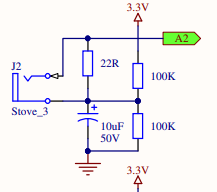
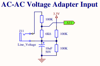
n of these input circuits:
1 of these reference circuits:
Connect them to any microcontroller that can handle n+1 ADC channels.
Use “EmonLib.h”(its C/C++ and there is no hardware specific magic going on is there?) to calculate accurate power values from input and reference circuit values
Use data somewhere - an exercise to readers imagination
If you can get a processor/microcontroller that has an analogue input that goes from 0 to less than 3.3 V, then use that - ideally 0 - 1.5 V. You can always reduce the voltage across the burden resistor by reducing the value of that resistor - and the c.t. will be more accurate (but any electrical noise that gets in will be greater in proportion).
Yes, there is a small bit of AVR magic, in emonLib.cpp. ADC_COUNTS should be obvious, the deeper magic is at the end. Look at lines 228 - the end: long EnergyMonitor::readVcc() {
This measures the voltage of the (stable) internal 1.1 V reference against the supply voltage (the ADC reference) and therefore calculates the (3.3 V) supply voltage. It was put there for when batteries are used to power the emonTx, and the supply varies as the batteries age.
If you have a stable 3.3 V (or whatever) supply voltage, you can #define emonTxV3"
in your sketch and it assumes exactly 3.3 V, or you can change line 70 in emonLib.cpp to tell it your ADC reference voltage exactly.
My imagination also says that if the processor you choose has a 1-wire input, you could measure tank temperatures etc with a few DS18B20 temperature sensors, and monitor & record those too.
the idea is to route data from “power brick” to master controller and then to a RaspbegryPi that acts as a webserver.
This is a DIY reef tank controller project its in initial planning and parts ordering phase still Because I’m cheap and I’m bored.
There is a master controller because I’m planning a couple of modules more (another power brick, water chemistry probe box) + a couple of switches, and water level triggers and I want minimal UI/info screen so need it visible while all others will be hidden
Back to power - I plan on using a battery backed up ~50W 12V meanwell psu to power all arduinos/smt32/microcontrollers. And then use dc step down converters if I need 9, 5 or 3.3V … how good an idea is that?
That 9AC reference input will work perfect as no power alert trigger.
Thanks for temp probe link - all I found were metal ones … not great in saltwater
Noise on the output might be a problem - you may need good filtering to remove it.
Ours are stainless steel. Or you could encapsulate the sensor itself in glass, using silicone heat sink compound or silicone grease to transfer the heat between the glass and the sensor.
That would give you more output voltage to feed into the ADC, but it needs a 5 V supply, and presumably the output is centred on 2.5 V, so it requires a 0 - 5 V ADC input range. Again, if the 5 V is not clean, then noise on that will get onto the output and appear as a current.
That appears to be a different device (5 A : 2 mA), and less suitable for what I think you need.
If some of the loads he wants to measure are in the aforementioned range,
he could pass multiple turns through the CTs connected to said loads, could he not?
(the thinking here is the wire for loads of that size should be fairly small)
I took a peek at my local electronics online stores no CT’s no VAC adapters … I’ll go to a local store and ask directly but it seems like for these things it’s international shipping … Covid-19 … bad timing
But the main issue with the module is it’s rated at 50 Amps. Given the fairly small rating
of the loads you want to monitor, you’d be better served by using something like this:
I didn’t see any reference to Modbus on the page the device is listed on.
What was it that made you think it’s a Modbus device?
Thanks for interest bull but I think you have things mixed up:
As you correctly noted ZMCT103C is much better for my application and that is why https://www.innovatorsguru.com/ac-power-measurement-using-arduino/ uses it for ac current sensing.
if you scrolled down on the article you will find that there are images of a device that uses both ZMCT103C and ZMPT107 (can’t find aliexpress link … I’m pretty sure i saw it on aliexpress) - as I understand ZMPT107 provides the same functionality (reference AC signal) as an 9VAC adapter for Arduino emonTx Shield.
At this point my plan is to get an arduino mega, 10 pieces of ZMCT103C, 1 unit: ZMPT107 + relevant passive components.
Are there any reason I could not use a ADC expander modules?
Are there any benefits of using higher precision ADC?
Ah, I see it now. I didn’t scroll down the page far enough.
Yes, you will need a Modbus to TTL interface to use it with an Arduino.
Something like this:
As far as I can tell, the ZMPT107 is a current transformer, with a ratio of 2 mA : 2 mA.
To use it to measure voltage, you must use a multiplier resistor in the primary circuit to convert the mains voltage to a current, and you must use a burden resistor (or a current-input op.amp) to convert the output current into a voltage.
I have seen modules using this, my concern with those is they appear to rely on a single component for the multiplier resistor, so that single component must have an adequate voltage rating for the peak value of your mains voltage.


 no CT’s no VAC adapters … I’ll go to a local store and ask directly but it seems like for these things it’s international shipping