As Robert pointed out…
From https://5nrorwxhmqqijik.leadongcdn.com/ZMPT107-1+specification-aidiqBqoKomRilSqqnnkikq.pdf
As Robert pointed out…
From https://5nrorwxhmqqijik.leadongcdn.com/ZMPT107-1+specification-aidiqBqoKomRilSqqnnkikq.pdf
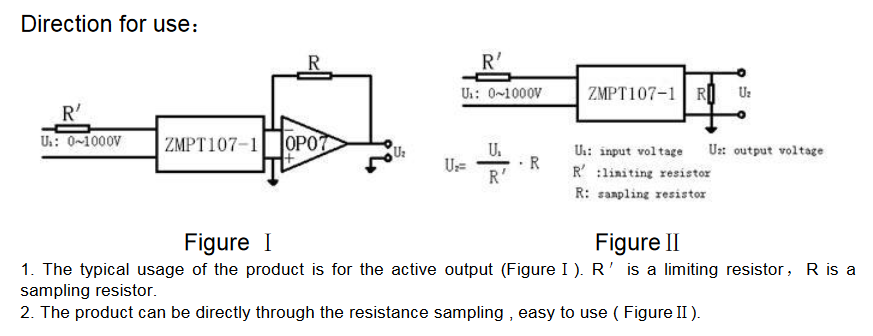
So from Figure 2 schematic:
Uz = U1 / R’ * R → 5V = 230V /R’ * R
any pointers for R and R’ values?
R’ = 46 and R = 1 ohm  ?
?
I think I need to use peak and not effective (230* 2^0.5) so that woudl make R’ = ~67ohm, or am i mistaken?
I need 8+ of those and to feed data to separate controller ![]()
It’s a modbus device, so that wouldn’t be a problem.
Cost for 8+ of them would be. Bummer.
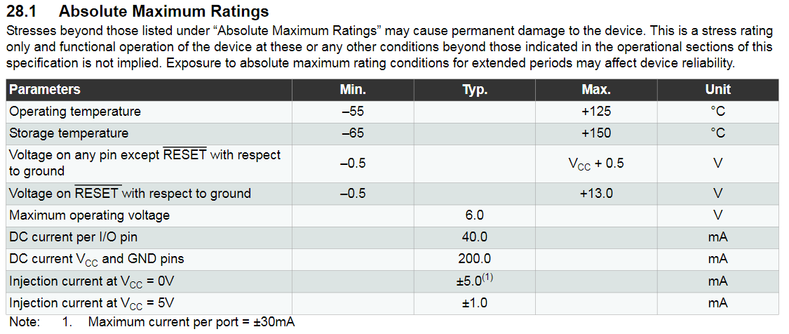
Conventionally, everyone uses rms values unless they say otherwise. The c.t. expects 2 mA. If the winding resistance is 100 Ω, the IR drop is 200 mV, so we can ignore it - the error is 0.2 in 250. Your maximum mains voltage is 230 V + 10% = 253 V, so your multiplier resistor R’ = 253 / 2 mA ≠ 46 Ω ![]()
The correct value will be 126.5 kΩ - I would use 2 × 150 kΩ in series to be more sure that the voltage rating of a single component was not exceeded if you get a spike on your mains. Do not use 46 Ω – you will burn out the c.t. almost instantly.
R will be calculated from the voltage you want at your ADC input when the mains is 253 V, but subject to the VA rating of the c.t. - which we don’t know. But the maximum resistance is given as 200 Ω. That will give you 200 Ω × 2 mA = 400 mV rms, or 1.13 V peak - peak. That’s not too bad for an ADC with a 3.3 V reference because you only expect the voltage to vary over a small range ( 207 - 253 V).
![]() that was just a straight forward formula calculation, R = 1 (obvious since I had no idea what to peg it at
that was just a straight forward formula calculation, R = 1 (obvious since I had no idea what to peg it at ![]() ), U1 = 230 (mains), output Rz = 5v (arduino), and bam = 46 ohms
), U1 = 230 (mains), output Rz = 5v (arduino), and bam = 46 ohms ![]() I must admit I almost immediately thought … wouldn’t that 46ohm resistor create an insane current on 230V mains well duhh
I must admit I almost immediately thought … wouldn’t that 46ohm resistor create an insane current on 230V mains well duhh ![]() thanks you for the numbers
thanks you for the numbers
Did I understood correctly that even though Arduino uses 5v inputs I can not pass ±5V signal to it’s ADC?
Also I visited local electronics shop and all they could offer me is a 250VAC to 9VAC 0.2A transformer in a PCB mounting package. No CTs and nothing remotely matching ZMPT107 specs.
So I’m doing my shopping on aliexpress ![]()
But then I found a this with a description:
https://www.aliexpress.com/item/32807375565.html
and a description Redirecting...
Does it matter that they are using it for 120V?
It’s just a ct and a resistor connected to an analog input and ground in parallel.
And not:
Also  what do you think about tools like http://lushprojects.com/circuitjs/circuitjs.html as a first test against magic smoke. How far from reality would they be?
Is this a good representation of CT current sensing?
http://tinyurl.com/rpczcmq
Correct. The voltage can go from 0 V to +5 V, that is 2.5 V ± 2.5 V, or 2.5 V d.c. with an alternating voltage of approx. 1.76 V rms sitting on it - as per the diagram in ‘Learn’:

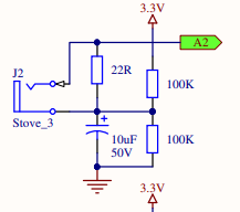
That appears to be YHDC 5 A : 5 mA c.t. with a 200 Ω burden. It replaces the jack socket and the 22 R resistor on the Boardman diagram.
But in the process of checking exactly what you have there, I noticed that the YHDC TA12-200, which is a 5 A : 2.5 mA c.t., has a maximum burden value of 800 Ω. That would give you 2 V rms at 5 A, more than enough for a 5 V Arduino if you are using the full 5 A (you’d need a burden of 620 Ω to give you a small safety margin) but would read a maximum of about 4 A with the 800 Ω burden (again allowing a safety margin).
Only when you’re looking at the quality of the insulation on the c.t. – which shouldn’t be an issue anyway as you’re not putting it on a bare conductor. The voltage on the conductor doesn’t have any effect on how the c.t. operates, it’s only the current flowing in the conductor that it responds to.
They are only as good as the information you feed them with.
They won’t help you design your circuit, but if you get it right, they will confirm operation is what you expect - or not.
Hmm…
It’s a pretty picture. I’m not sure of its value though. But then I’m a card-carrying cynic. When I learned my electrical engineering, the university department owned one computer, a PDP11. And I don’t think they had that until my 3rd year.
I’m hope I’m not pestering you too much And those graphs definitely help me visualise what is going on - I’m a just a lowly applied mathematics BA 
I recreated the schematics (remembered that * and + in crossing wires are different :D) and I see what is going on.
So you will not believe this but I have more questions
We are only interested in peak current value when we are measuring normal mains power right? Why are we splitting our adc resolution range by adjusting our signal with an offset of +2.5V. Does arduino ADC freak out if we apply negative voltage to its input? The Ta12-100 example seems to do just that.
Also what is the function of the capacitor in it seems to add offset slowly - is there some sort of voltage spike on power on, if we remove it (circuit simulator does not show it)
Not freak out. More like smoke, as in the Magic Smoke you mentioned earlier.
Applying anything more negative than -0.5 VDC to the ATMEGA 328 analog inputs will damage it.
A capacitor acts like a short circuit to alternating current, but an open circuit to direct current. Let’s ignore for a moment what happens when you power up, and concentrate on what happens when everything is stable.
There is no a.c. voltage present. The midpoint (our diagram) sits at 2.5 V, and ADC input likewise. Now turn on the mains power, so that an alternating voltage appears across R1. For the full voltage to appear on the ADC input, the midpoint must not move. But R3 and R4 are large compared to R1, so the midpoint voltage might get pushed about. This is where C1 comes into play. It grounds the midpoint to the alternating voltage, holding the midpoint firmly at 2.5 V.
What happens at switch-on (of the 5 V)? Because the capacitor doesn’t want to let the voltage across it change, the midpoint voltage will crawl up slowly to 2.5 V. So yes, that slow build-up is a necessary side-effect. It’s not something we want, we have to put up with it.
Ok - but we are only interested in peaks right? Could we not somehow clamp the negative side of a signal or use a rectifier (I think that that what it’s called) to invert negative side.
Edit.: from emonLib it seems we only interested in Peaks and Oscillation counts - am I wrong?
Edit2: How about something like this: http://tinyurl.com/sbyvla8
and use the whole resolution for peak measurement? We could add a slight offset to guarantee minimum is >0 V but I don’t suppose -0.5mV matters
Edit3: There 
http://tinyurl.com/ukosg7h
5 V design full spectrum and non-negative 1.3mV baseline. Did I miss anything?
Wrong.
Wrong again. The wave is sampled about 55 times in each mains cycle (for our emonTx and emonPi) and the averages are calculated. That way, you get an accurate measure even if the shape of the wave is not what you expect.
If you want the details:
Real Power = (Σ (Vn × In)) ÷ n
VRMS = √ ((Σ Vn²) ÷ n )
IRMS = √ ((Σ In²) ÷ n )
Apparent Power = VRMS × IRMS
in each case where n is the number of samples over an integer number of mains cycles.
Hum ok so cutting off negative half (is that the technical term? :D) is not good - how about inverting “-” to “+” axis?
Does it matter if if have double the pulse? all we are doing is a rough integration according to formulas. So what if the signal is weird - it will just be double weird on the same side of the axis the sum and the avg. is the same.
Technically we could take a data set and then alternating bumps turn back into normal wave set (0,1,2,3,2,1,0,1,2,3,2,1,0,1,2,3) → (0,1,2,3,2,1,0,-1,-2,-3,-2,-1,0,1,2,3) its just the adc that does not like negative number
the only problem with this is that you would probably need a smarter/faster controller preferably with DMA and simultaneously take U and I data sets.
Do you want to know the direction of power flow? If you do - and for anyone who is in a position to export energy as a product of private generation from hydro, wind or (more usually in the UK) PV - then knowing that is an absolute necessity. As soon as you rectify either current or voltage, which you are proposing and which happens in the maths when calculating the rms value, then you lose that ability.
I don’t understand what your objection is to taking well proven code and just using it.
Well - you said it yourself for low power situations like mine noise is a problem, so I’m looking for ways to improve it or at least make a worthwhile trade-of as in this case - direction does not matter in my case.
And since my parts shipment is 1 month away I’m sitting here theorycrafting
In your opinion is 35mV for ~10W (46mA) too low for a reliable measurement?
I presume higher ADC precision (12 or 16) would not really help in dealing with noise?
35 mV should be OK if you’re careful with your circuit layout, and you have clean noise-free power supplies. The problem with noise is, once it has got in, it is very difficult to do anything about it.
Thank you Robert for the info and the patients
Once I get my order I’ll build something and maybe then will have more constructive questions if you don’t mind