A quick share on getting an MCP3202 working with ESP8266. I’m using it for my DC project.
It’s different from the MCP3204 and MCP3208 so needs slightly different code.
Using SPI protocol to interface and ESP with an external 12-bit ADC, which has higher resolution than the standard ATMEGA328 or ESP12S 10-bit resolution.
https://nodemcu.readthedocs.io/en/master/en/modules/spi/
This site references the pinout, and in the code the chip select is 15. Other pins can be used to put multiple SPI devices on the same CLK, MOSI, and MISO pins, but different Chip Selects, which economises on wiring.
In my example the 2 channel ADC has a resistor divider dividing the reference in half for one of the channels.
Multi-channel ADC’s like these could be used for a variety of purposes, light sensors, temperature sensors, etc.
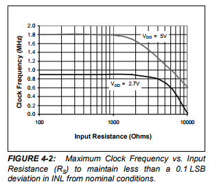
Here’s page 15 from the MCP3202 datasheet. From this the relationship of the bits transferred via SPI and the chip’s requirements can be further understood.
The 3202 is a two channel variant of the 3204 and 3208, and examining the datasheet, has the same operational characteristics. There are a few things you might investigate to improve your results with the ESP8266/MCP320x combination:
The ADC uses a sample-and-hold capacitor to take a sample of the input voltage for conversion to digital. The sample and hold period using your code is 1.5 SPI cycles. For any desirable SPI speed, that requires special handling to get the capacitor to fully charge.
The datasheet talks to this point, and references figure 4.2:
You can see here that as clock frequency goes up. the impedance of your bias voltage will need to be progressively lower in order to fully charge the S&H capacitor. The graph suggests that 1K is about the maximum. I have a hard time with colors on resistors but it looks like you are using 10K for the voltage divider. That will cause sag in your readings.
Those are a few things you can do to get excellent results given these limitations:
First, using an opAmp to produce the bias would completely solve the problem.
Another option is to use lower value voltage dividers, like 1K.
Adding a 10uf capacitor between the ADC input and ground will also help to “jump-start” the S&H capacitor.
You’re right that there is a subtle difference in the SPI transaction vs the 3204 and 3208, but the sample and hold period is defined the same way and the technique can be adapted to this variation in the SPI transaction.
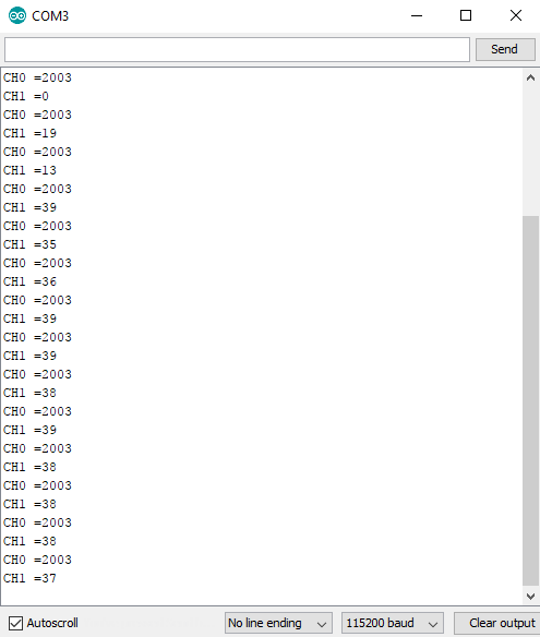
I did have unexpectedly low readings so it’s affirming to have a few thoughts confirmed on the sample and hold issue, I considered lowering the clock speed using DIV32 instead to make it 2.5MHz (is that the best way of setting clock speed I wonder?).
I’ve just tested DIV32, much better… very slight deviation with DIV16, however with a much lower than 10k resistance I’m sure the reading would be as expected.
I see in the datasheet now the flexibility of the MCP320x in terms of clock timing, it doesn’t need a rigid clock speed, meaning the sample and hold time can be made longer, which is what you’ve done in software.
I thought to use a cap to ‘jump-start’ like you mention, has this worked for you?
The op-amp solution looks good, there’s a recommended chip in the MCP320x datasheets, the MCP601.
The current sensing chip LMP8481 I’m using for my DC project I see has a ‘Buffered High-Output Current > 5mA’ which I translate as having an output resistance of 1k @ 5V maximum. So it’s just acceptable I think.
Because 5V is required for the LMP, I’m maximising on clock speed connecting the MCP320x to 5V also. I’m not completely confident on running the ADC at 5V and the ESP at 3.3V in terms of SPI voltages. What did you make of this?
They looked low to me as well, but were within the realm of possibility with the 5% resistors, so I can’t say. You can measure the actual divided voltage and the reference voltage and determine if it’s reasonable.
I don’t know if they implemented the clockdiv method to set SPI speed. I know the metal is not that simple on the ESP. I use beginTransaction(SPSsettings(2000000,…)) . 2.5MHz is pretty fast for that chip, even at 5V.
It helped a lot when I was using voltage divider resistors. I use an opamp now.
Might work OK. I use the venerable LM358. Had problems with another in that it oscillated a bit at harmonics of the AC frequency. If you are a good EE, you can probably figure out why. I tried a few things, then went with the LM358 which has been solid.
I ran the 3208 on 5V for awhile. The CLK, MOSI and CS come from the ESP and are 3.3V signals, which the MCP3208 accepts fine at 5V. The MISO on the other hand is generated by the MCP320x and is a 5 volt signal. I knocked it down with a resistor voltage divider. It’s not the recommended method, but the simplest. It worked fine at 2Mhz SPI speed.
That said, the MCP3208 works fine at 3.3V and 2MHz SPI, so if you can get by with an Aref of 3.3V that may be the way to go.
Same, dividing down the MISO I figured and have got on the board as a 1k/2k divider.
The advantage I can find for working the LMP and ADC together at 5V is the improved resolution relative to any noise.
So simply bringing the MISO down a level seems the way to do it.
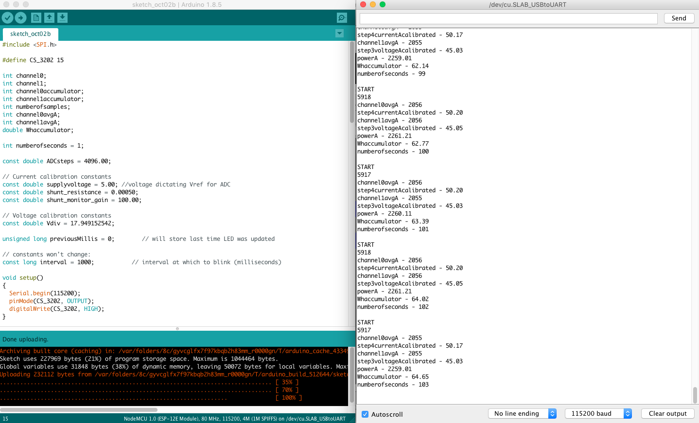
Over 5910 samples per second at the moment, for this basic sketch…
I’ve got a bunch of defined constants in the code to make an allowances for changes that could happen IRL… Code constants for real life variables?? Such as the shunt resistance… which could be changed given the current ranges aimed for.