Are you familiar with these…
NodeMCU module & MCP3208 DIP :
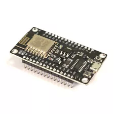
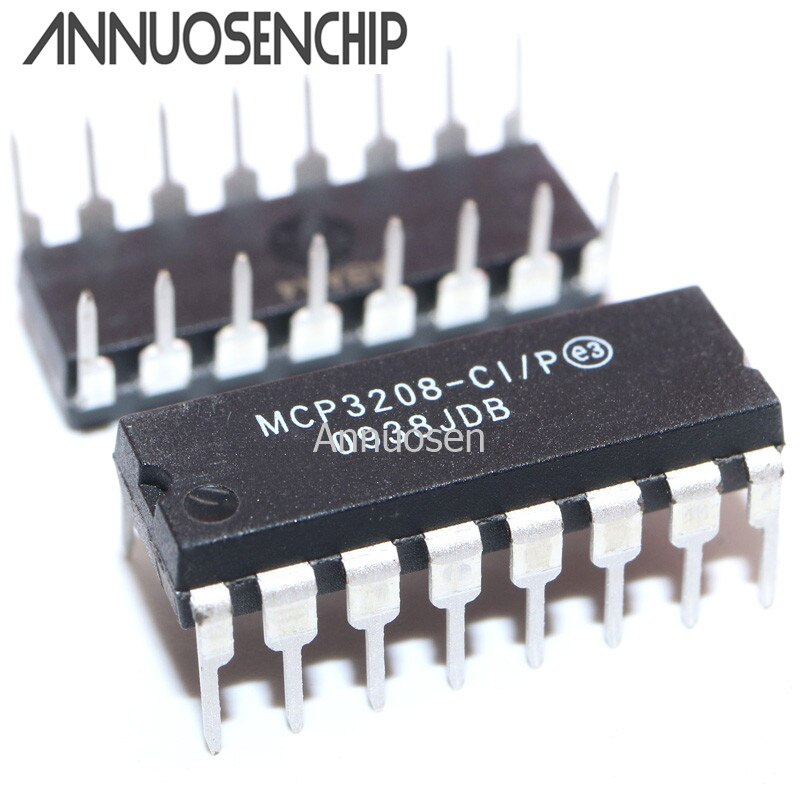
These two components could be the basis of cost-effective voltage monitoring over WiFi, plus stripboard, wire, solder perhaps, and common resistors, capacitors, and a 5V supply.
Depends how DIY you want to get.
Just remembered I documented some of the process here:
. MCP3202 ADC, SPI and ESP
The latest PCB has been simplified to a resistor divider with a capacitor for filtering.
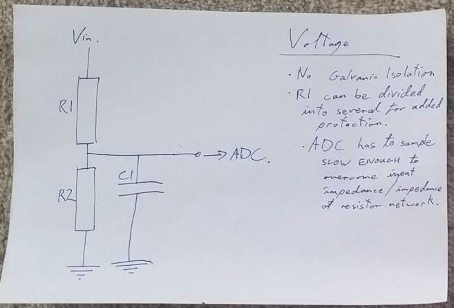
(no input protection shown)
and then frequency response is worked out using R2 and C1, assuming R1 is much much greater than R2, which is probably what you want.
and then the ‘high impedance source to ADC’ problem is solved by having the ADC sample slow enough, that’s done in firmware with entering an SPI clock speed. The speed I’ve chosen is good with R2 at 75k, although C1 helps so without calculating it’s hard to say exactly what sampling rate / impedance combinations are accurate.
That help?