Hi there! Just a couple of weeks in to using emonPi2 with 6 CTs and 2 temperature sensors. All going OK so far. I also got an optical pulse sensor so I could compare and calibrate my electricity total feed CT with the LED pulse/kWh on my Linky meter here in France. But despite the green LED on the optical pulse sensor flashing when stuck over the meter LED I get no counts in the s/w.
I have checked the config etc. using serial monitor and it is enabled. I next unstuck the sensor and just flashed my (white LED) pocket lamp at it - it counts up just fine!
I’ve tried repositioning the sensor and without the sticky ring, but no counts! As I said, the green LED on the sensor flashes with the meter LED, but they aren’t counted.
I have two theories - either the sensor is insensitive to the yellow LED used in the Linky meter - but then why would the sensor LED flash? Or the light pulses emitted by the Link are too short to trigger the pulse counting? Is there a parameter to adjust the sensitivity or duration of the pulse input.
Did anyone succeed in optical pulse counting with Linky? Is there a trick I missed?
Pulse counting uses interrupts to the AVR-DB processor, and as the pulse is long enough for you to see, I don’t think this is the problem. It is much more likely the light level is the problem - the optical pulse sensor is purely an amplifier, and we also know that the output goes “high” before there’s enough light for the LED “repeater” to come on. This makes me wonder whether ambient light is reaching the sensor, and you have a permanent logic ‘high’ - or high enough not to register a ‘low’, if that makes sense. If your meter is in a dark place, them I am wrong.
Thanks for your reply Robert. It looks like I’m going down a path that has already been trodden. The meter is in my basement with a little bit of ambient light, but not much, and it doesn’t work at night either when it is pitch dark - even the street lights here go out at 11pm - never woken up to any pulses!
So from the links you sent it seems that lack of sensitivity is probably the cause, rather than pulse duration, as it’s just looking for a rising edge.
I suppose that to prove it I need to get out my ‘scope and check what voltage level is appearing on the input line.
Was there a resolution for increased sensitivity if that is the problem - either by tweaking the circuit or even maybe adding an ‘optical repeater’ to make a bigger flash?!
I will report back when I’ve had time to set up the scope down in the base!
Not necessarily. From the emonLibDB documentation (the library which does all the work):
void EmonLibDB_setPulseMinPeriod(uint8_t channel, uint16_t _period, [uint8_t _edge=FALLING])
Sets the minimum period of time that the pulse must be active and in a steady state to be
recognised, in ms. This must be shorter than the duration of the pulse. (Note: this differs
from the definition in previous releases, and if the period is specified, its value should be
reviewed.) For electronic switches that do not exhibit contact bounce, zero may be used.
The channel number (one-based) defines the input to be used, and must be specified if
edge is specified. Input channels for the emonTx V4 are: 1 – ‘Pulse’, 2 – ‘Digital’, 3 –
‘Analog-Input’ – alternatively the names ‘Pulse’, Dig’ & ‘ADC’ may be used. The
appropriate solder links must be made on the p.c.b, and the ‘Analog-Input’ pulse input is
not available when the extender p.c.b. (c.t’s 7 – 12) is fitted. The edge on which the pulse
is detected may be specified if required (RISING or FALLING). Default: period = 20.
It is most unlikely that Trystan has given you easy access via the Admin page in emonCMS to these parameters, so to change any of the parameters, you will need to download the sketch, edit it, compile and reload it into the “emon” board of the emonPi2. Normally the optical pulse from a meter is about 100 ms long.
The relevant lines in the sketch are:
  EmonLibDB_setPulseEnable(false);              // Enable counting on "Pulse" input
  EmonLibDB_setPulseMinPeriod(20);             // Contact bounce must not last longer than 20 ms
Are you using the “Pulse” input, and have you enabled pulse counting?
Note that “Contact bounce must not last longer than 20 ms” might mislead you. A more accurate description would be “The pulse must be stable for more than the Minimum Period”. The timer is reset every time it sees a change of state, and only counts a pulse when it times out. This will only concern you if the pulse is shorter than 20 ms, because the optical sensor does not have contact bounce. You can set the period to zero when you have an optical sensor.
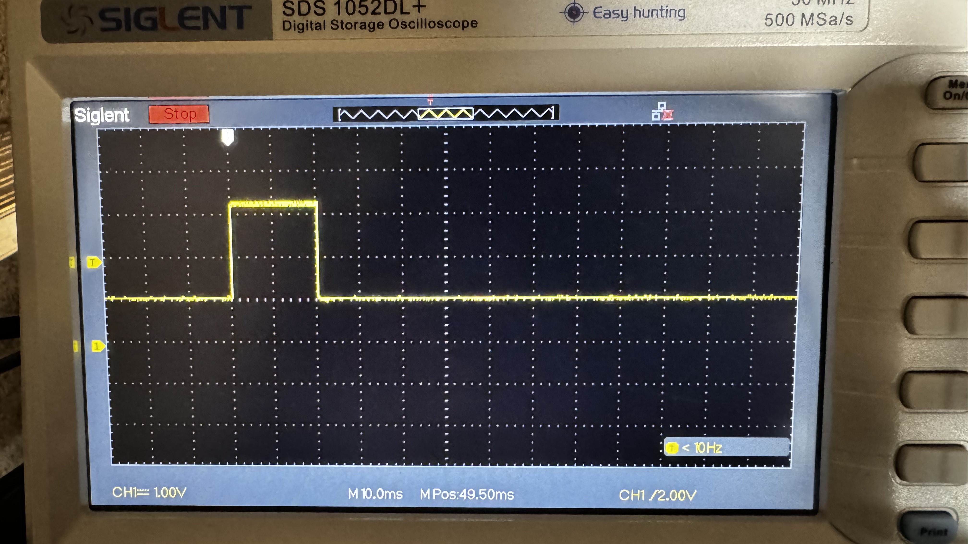
Hi Robert, thanks again for your help. I checked the pulse amplitude and duration this morning - see photo. Looks like the pulse is about 2 volts and duration about 20 ms. I don’t like the way it tails off though, might be difficult for s/w that’s looking for a falling edge? The pulses are 100% reliable and no glitches or noise visible in between. I tested in the dark as well as with the (dim) lighting in the basement, no difference seen.
You can see that by the time of the falling edge the voltage has roughly halved, as if it’s charging a capacitor on the input. I can experiment with pull-up or pull-down resistors but not sure that would help.
Was your 'scope d.c. coupled? In any case, the default “de-bounce” time will mean you cannot rely on detecting 20 ms pulses. You must change EmonLibDB_setPulseMinPeriod(20); to EmonLibDB_setPulseMinPeriod(0);
I don’t have an emonPi2, so I cannot be certain of the steps you need to take to make the change. I don’t even know which sketch is the factory default - it’s not published anywhere that I can see, and what appears to be the default under the heading “Available Firmware” on this page emonpi2/firmware at main · openenergymonitor/emonpi2 · GitHub is a bad link (404). @TrystanLea Can you make this parameter available via emonCMS, or advise @RichardinCancale which sketch he needs to change.
Also, is it possible that the RPi GPIO has become an output and it’s loading the optical sensor? It looks as if there might be a load of around 1 kΩ pulling the pulse down.
Thank you Robert. Scope was AC coupled BTW. Certainly if it’s to be used in France where there is only one type of smart meter - Linky - then this needs to be parameterised if possible.
Another idea - I could try and stretch the pulse by sticking a capacitor across the input to ground, but maybe then there wouldn’t be enough of an edge to trigger on?
It should look better d.c. coupled. There’s no a.c. coupling in the optical sensor.
It’s triggered on level - without delving deeply into the AVR-DB data sheet it looks like 0.7×VDD for a ‘HIGH’ and 0.3×VDD for a ‘LOW’; these are max. values, so 2.0 V might not be enough - but I don’t understand why the pulse is only 2.2 - 2.3 V, it should go a lot higher if that output transistor is saturated, unless there’s a quite small resistance to GND loading the output - which there shouldn’t be, if the on-board link is set to ‘pulse’ and the ‘tmp’ link is broken.
By far the best solution is make the timer available to you.
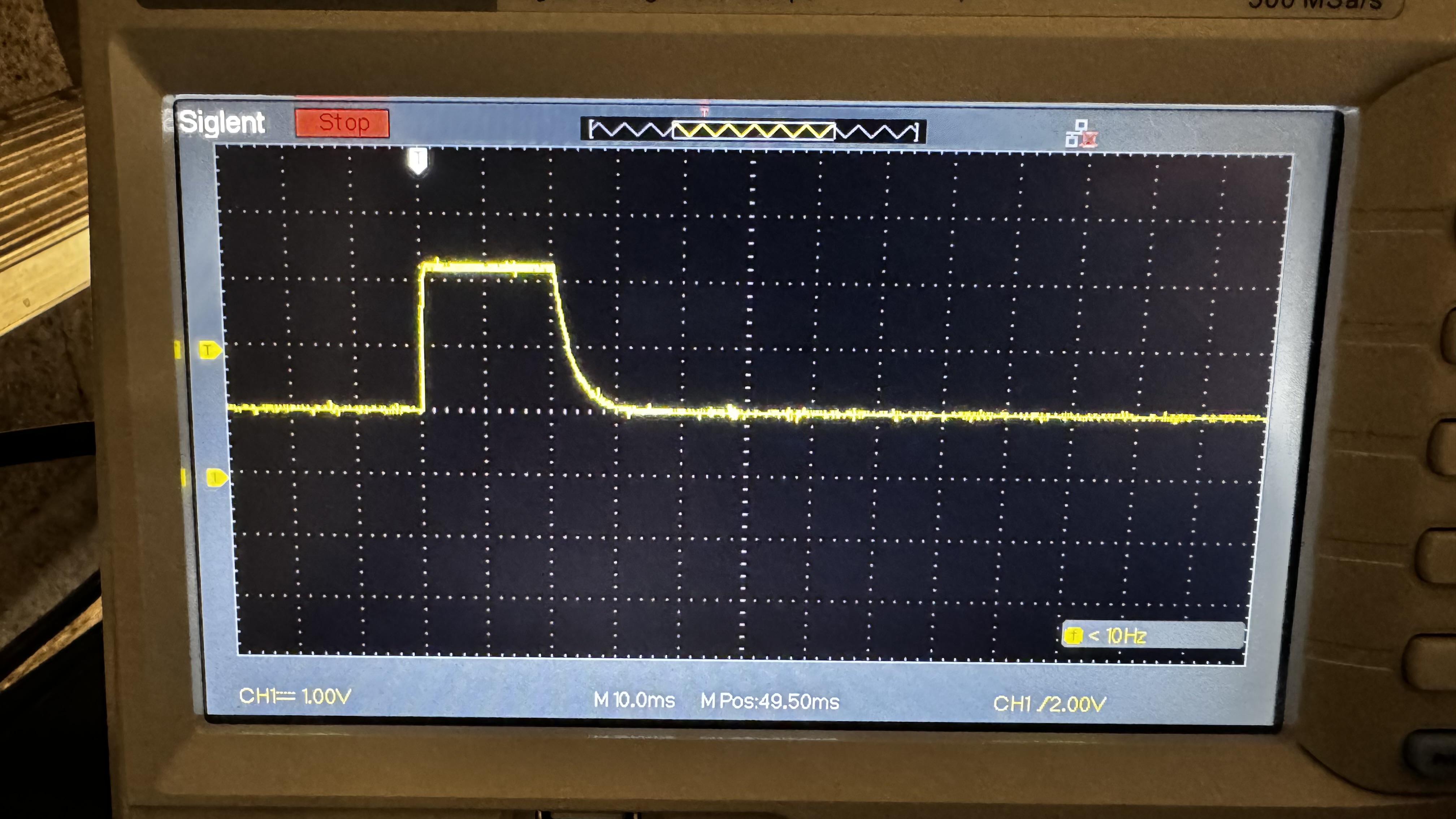
Hi Robert! Back after a 10km fast walk by the sea and had time to experiment a bit. I first tried putting the ‘scope into DC coupled mode as you suggested and the pulses do look nicer, although still only 20ms duration:
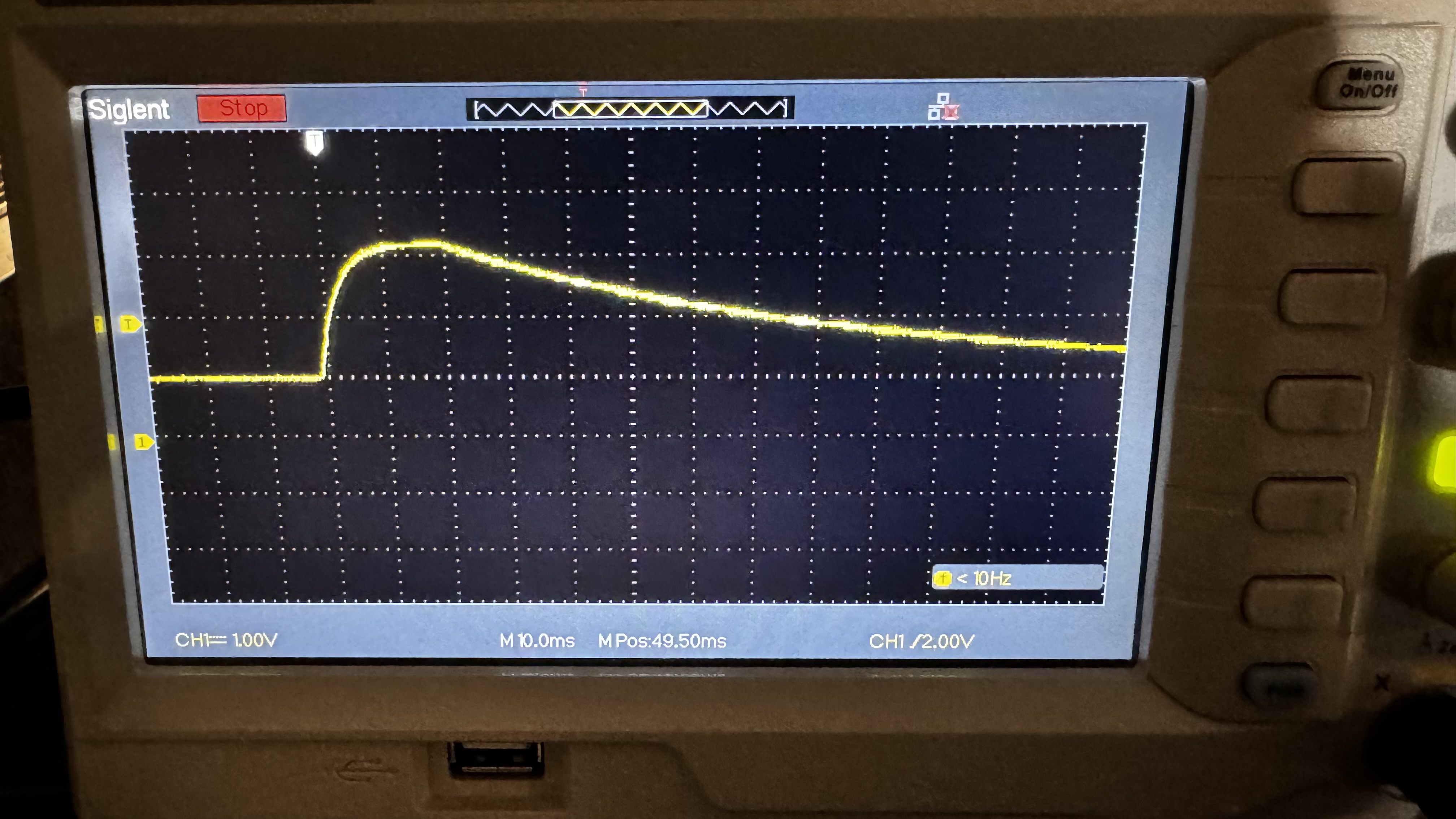
Works and pulses get counted OK! But that stretches the pulses to almost 100mS so maybe a bit much, depending where the cut off is.
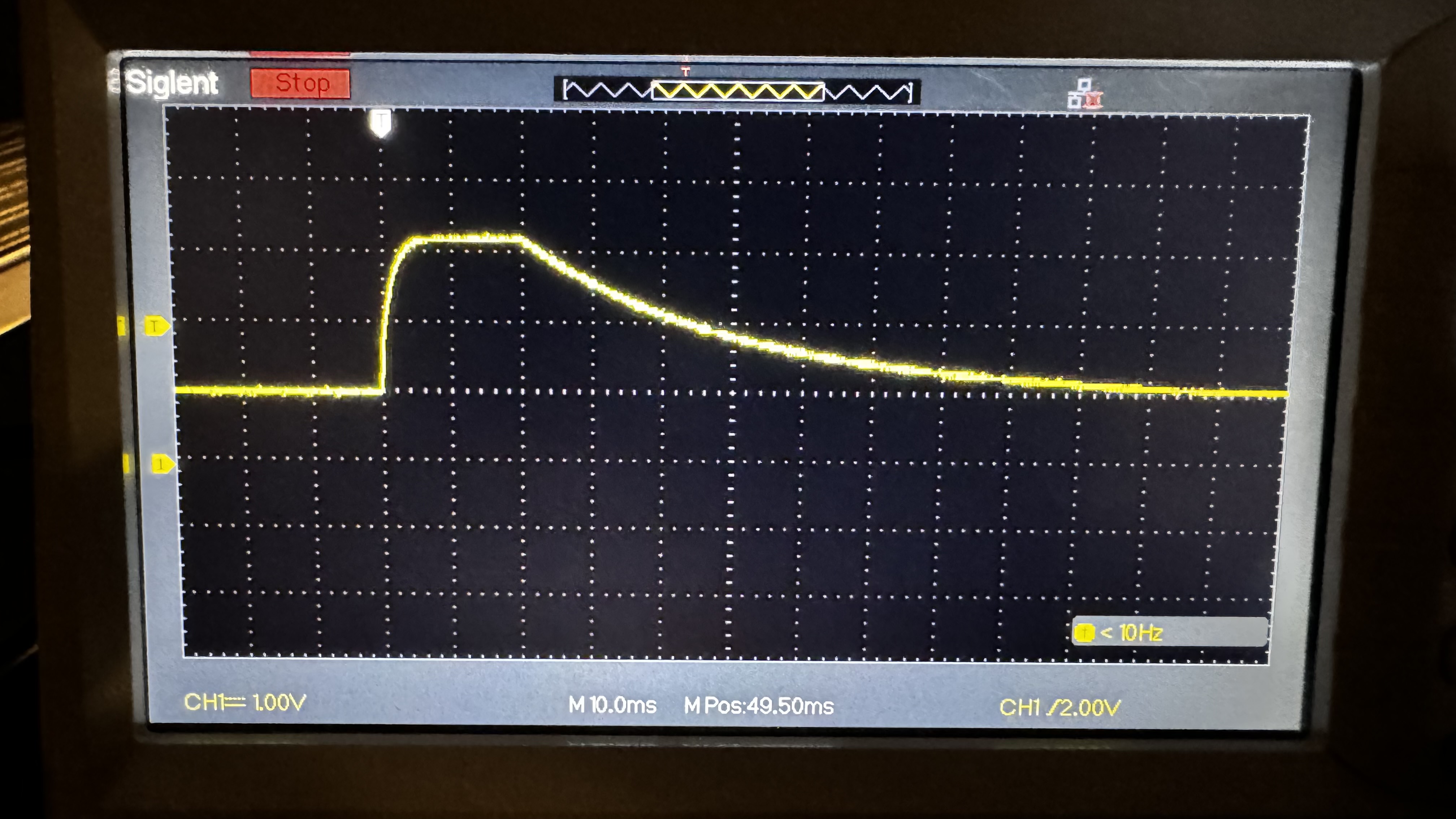
Finally tried 4.7uF as a compromise - still counts OK but about half the time constant. So I’ve left that in place and will do a longer term comparison between the meter reading and the Emoncms system.
Thanks again for your help. Without your knowledge that the pulse length needed to be >20mS I would not have succeeded! The capacitor solution is not as elegant as a software solution but it’s quick (and dirty!)
Just to finish this topic - I have tracked the kWh recorded by my Linky smart meter, by the CT clamp recording the total input to the house and via the pulse sensor counting the 1 Wh flashes on the Linky meter. The Linky meter only displays in whole kWh units, so the reading from the meter can be out by almost 2 kWh if you take the worst case - meter just counted up one unit at the start (X.001 Wh) and/or just about to count at the end reading (X.999 Wh). So up to almost 2% inaccuracy and on average 1% inaccurate.
After 4 days the meter had incremented by 124 kWh. The CT measurement at the exact same time incremented by 122.756 kWh and the Pulse counting (1 pulse = 1 Wh) showed 122.445 kWh.
Overall an excellent level of agreement with the meter reading 1% higher than the CT (but allow for the meter reading being at worst 2% out) and the CT and Pulse counting agreeing to within 0.25%.
A couple of weeks back (I should have noticed this thread at the time!) I was trying to help another customer with a pulse counting issue, that I have not actually been able to resolve, LED on the pulse counter flashes and I tried adjusting the pulse duration with no avail.
As such there are now a range of pulse width firmware examples available to download:
I know this is not the elegant way to do this and yes I should make this an editable option! I need to revisit why changing the data logging interval e.g d9.8 is not saving as well!
Hi Trystan - thanks for taking a look at this. As I discovered French Linky meter pulses are only 20ms long (1pulse = 1Wh) so flash the LED but don’t get counted in the default set-up. I solved this by stretching the pulses using a 4.7uF electrolytic capacitor across the data & ground pins at the plug end. This should be good up to around 5 pulses per second = 18 kW load.
As my monitor is working live I’ll stick with the hardware solution for now until the summer when the heat pump is off.
There was a reason for allowing a value of zero as a parameter into the library call, when the minimum period is zero, it completely ignores any timing considerations and works solely on the edge (rising or falling as specified).
For optical pulses in general, and from what @RichardinCancale writes concerning the ‘Linky’ meter in particular, the pulse counting should be set up with: