I have been using an emonpi for several years now and am very pleased with it.
My panels on my shed approx 25m away from my meter box , My emonpi at the meter box has two clamps , one on my cable from the shed (solar) and the other measuring import from the grid .
I have just bought a 2nd hand electric car which I trickle charge in the shed . As I only have one main line from the shed to the meter box , the solar measured at the meter box is incorrect as the power used in the garage subtracts from the solar output.
Can I move the solar clamp to the shed and connect it to the emonpi with data cables?
A data cable was run in conduit to the shed when the the solar was installed and the inverter has a sensor on the meter box to measure voltage and import current . There are spare pairs available.
Rob
Hi Robert, welcome to the forums.
There’s a few topics here where this has been discussed, try searching for “CT cable length”, or “extend CT”.
“CT” stands for Current Transformer, which is the correct name for the “clamp” you’re asking about
Here’s a few results from a brief search I just did using those suggested terms:
If after searching you end up with specific questions, certainly feel free to elaborate in this topic with more details.
There’s a full article in ‘Learn’ - linked in the second post @Greebo has quoted.
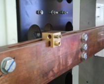
And indeed, as an electrical engineer, the only type of clamp I understand is one of these – a busbar clamp:
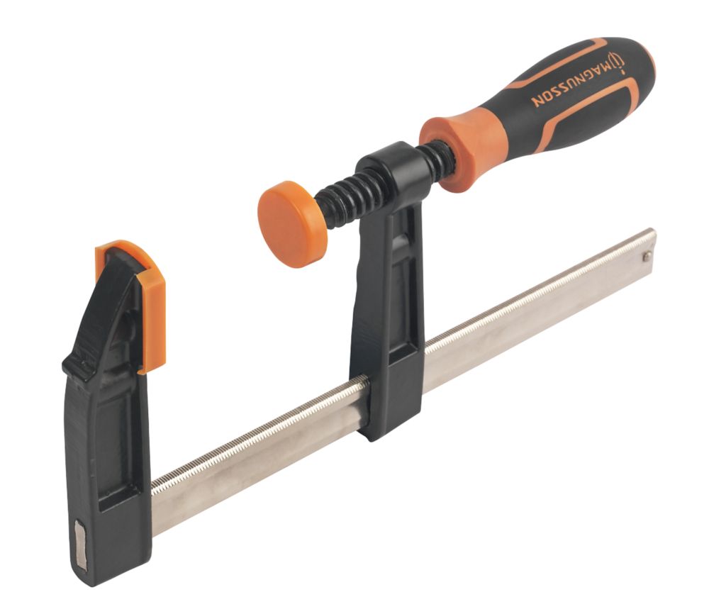
But a woodworker friend uses these:
Robert
I think I should have used the word CT sensor. I’m a civil engineer more used to bulldozers and scrapers and not up to speed with electrical terminology. I am , however , very interested in renewable energy , micro-grids and community batteries and am learning more each day. I believe the solution to my problem is relocating the CT sensor to the inverter using a suitable data cable with twisted pairs.
Rob
I have, for the past 50+ years, only ever used “current transformer”, usually abbreviated to c.t. That covers both solid core (or ring core) and split-core types, and for most of the time, it’s not necessary to distinguish between the two. I object to the term “clamp” because a ferrite-cored split-core c.t., such as the 100 A one stocked by the OEM Shop, should never be clamped to the cable, which some users seem to believe is necessary. Because the core is ferrite, a very brittle material, it is all too easy to snap the core, which introduces an air gap and effectively destroys the c.t. The only time a c.t. should be clamped onto a cable - or more usually a busbar - is when the manufacturer has incorporated a clamping mechanism into the design of the c.t.
I do recognise a clamp ammeter, which is effectively a meter movement and a c.t. that has spring-loaded jaws which do clamp around a cable, but that is the only time that “clamp” is acceptable when used to describe a c.t.
Hey Robert,
You can perfectly use the UTP or data cable as long as you use a twisted channel for each CT. I’ve been using a cable of around 20m to extend my sensors from one electrical board to the next board. You just have to calibrate the sensor with the same length of cable. I’ve done this by calibrating directly at my rpi and using a spare cable with the same length. I’ve created a small pcb with an RJ45 and some stereo connectors on it.
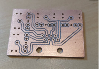
on the other end of the cable, I attached 4 stereo plugs to an RJ45 socket, one on each twisted pair. After calibration it’s been running just as smooth as the sensors directly attached to the pi.
What are you trying to say? If the cable length affects the calibration, then either you can’t be using a proper current transformer but instead are using one with an internal burden, or your extension is so long (and the voltage drop of the cable you’re using is so great) that the c.t. is working above its VA rating.
Unscreened cable might be usable on a short run with no serious sources of interference, but because the input circuitry of the emonTx and emonPi is unbalanced, and at low powers the voltages are in the millivolt range, I would prefer the minimal extra cost of installing a proper screened cable. If you already have a cable in place and replacing it or installing a new cable is difficult, then it’s worth trying to use what you have.
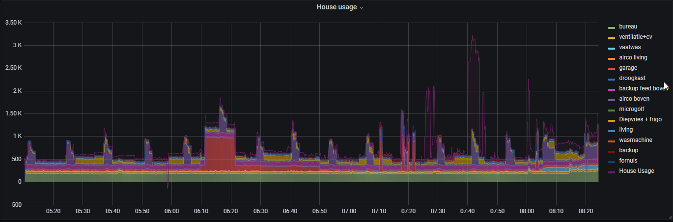
I’m using standard cat5E cable and one pair per CT. I’m using the SCT-013-000 current transformers. I tested the setup with and without the additional cable, measuring the actual power usage with a kwh meter directly connected to a power socket, that I connect to the breaker that will be used . There was a difference in the measurements with and without the extension, so I recalibrated the 4 sensors I’m using in the remote board. I don’t know the exact numbers anymore, but there was a drop when using the cable. I’m happy with the way the system is working now. It’s providing me a consistent view of my power usage:
The point about using a “good” low-resistance cable is that it does not add a significant amount of resistance to the burden that the c.t. sees.
When you use a thin wire (such as Ethernet CAT 5 at 0.2 mm²), what you’re doing is increasing the load on the c.t. and (generally) adding to the phase error. As the cable length increases, there will be little or no change in the amplitude error (i.e. the current) because the c.t. itself is a current source, and the voltage it generates will exactly compensate for the additional voltage drop in the cable, but the phase error will increase. Eventually, and depending on the current, the c.t. will saturate and when that happens, both amplitude and phase errors will increase rapidly.
I’m using the CT’s in the lower ranges (0-25A) and my voltages are 220-240V. My hybrid invertor with battery is connected to this remote panel. Most of the time this inverter is trying to keep the meter load at zero (if there is solar or battery power left), resulting in feedback from the battery or from the solar panels on one of the three phases or on all three of them. I haven’t seen loads above 6kw on either of the three phases, so I’m confident the CT’s aren’t saturating. I’m pretty sure that the phase shift does happen, I remember when calibrating I was trying to figure out why there was a difference when adding the cable, but in the end I didn’t bother as with the correct calibration parameters I got good readings compared to my kwh meter and I still had a lot of work to do, rewiring the additional panel and hooking up all the sensors in my main panel.