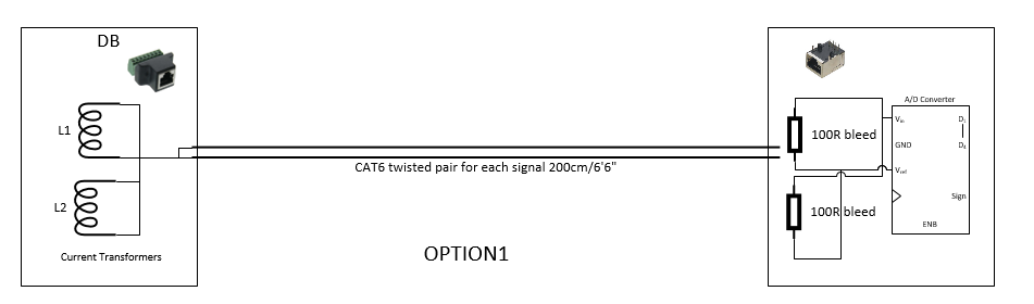
I assume that this is the right platform to ask regarding very basic and practical physical connection of current transformer to ADC. I have a TPN 3x8way DB and plan to use 2xmcp3208 and esp8266 to monitor few load currents and all 3 phase voltages. But all project items won’t fit inside DB and also esp8266 will suppress Wi-Fi signal inside metallic DB. So I plan for providing only current transformers and voltage transformers inside DB and using 2meter CAT5e/CAT6 cables to extend connection to mcp3208/esp8266 board located outside DB. The below are my 2 options also shown as diagram below
Bleed resistor outside DB next to ADC
Bleed resistor inside DB
in both cases I plan for CAT5e or CAT6 cable and RJ45 socket and jack for both sides.
Requesting your expert opinions on these setup.
---- My doubts
I prefer bleed resistor inside db (Option2) to avoid higher voltage risk while pulling the connector in either side. Does this setup effect on noise picked up by ADC?
Is it Ok to use RJ45 connector?
Is it ok to use each twisted pairs of CAt5e/cat6 for each current transformer?
If you are worried about high voltages from your c.t’s, the first thing to check is whether they have any internal protection, in the form of back-to-back zener diodes or similar. If that protection is present, the danger is minimised, and then there’s no problem in having the burden (not bleed) resistor at the receiving end. In theory, it should make no difference, but as the c.t. is a current source, it will generate whatever voltage it needs to overcome the cable resistance.
But in any case, I would not want to use CAT5/CAT6 cable because of the risk of breakage. I would be much happier with stranded conductors that are more robust.
CAT 5/6 cable is available in a stranded variant.
Jumper cables, like those used on a patch panel are stranded and available in various lengths
up to 200 feet, as well as in bulk.
Good article on extending cable. Cat 6 patch cable are available that is more flexible (it is using mostly stranded wires so breakage could be avoided).
Regarding protection I believe no Zener protection, the transformers are cheap and from Aliexpress/ebay. While a simple run without burden (sorry I written bleed) I was feeling slight irritation on hand while touching terminals. But this could raise to lethal voltage or not ?
What about RJ45 jack and socket.? I have at least 16 signal sources so totals 32 conductors. It seems easy to use RJ45 which only need 4 sockets else 16 sockets required.
You could of course add your own zener diodes at the source (c.t.) end, and have the burden at the ADC end. All you need is a zener (a pair, per c.t.) that is capable of dissipating the power that your c.t can deliver into it, and the voltage rating needs to exceed the peak burden voltage by a comfortable margin - You haven’t said what your maximum ADC input voltage is, but it should exceed that by enough to ensure there’s no appreciable zener current at that voltage.
If it’s a large c.t. (physically - with a big VA rating), then that’s possible. It’s unlikely with a very small one, but it’s never good practice to open-circuit a c.t. no matter what size it is. It is always safe to short-circuit one.
I understand the appeal - price! The specification I looked at rates the contacts at 1.5 A, so unless the secondary current of your c.t. is approaching 1 A, it should be OK. Personally, I wouldn’t use it much above 100 mA rms.
The specification I looked at rates the contacts at 1.5 A
With the number of devices available using Power Over Ethernet, that makes sense.
Conservative compared to the present day spec, the original was 350 mA.
The original IEEE 802.3af-2003[1] PoE standard provides up to 15.4 W of DC power (minimum 44 V DC and 350 mA[2][3]) on each port.
Looking at ways of increasing the amount of power transmitted, IEEE has defined IEEE 802.3bt4PPoE in September 2018.[11] The standard introduces two additional power types: up to 55 W (Type 3) and up to 90-100 W (Type 4). Each pair of twisted pairs needs to handle a current of up to 600 mA (Type 3) or 960 mA (Type 4).[12]
I have tested with around 3 meter CAT5 with 2 current channels and one voltage channel but used stereo jack and sockets. I observe no any noise pickup from cat5 since current reading shows almost 0.00A at no load. But I chosen 2 core shielded wires for easy connection to CT at DB side but not tested yet. It is preferable to connect each CT cable’s shield individually to earth before the stereo jack it self for the sake of safety, this is really I’m finding difficulty. I have to pull separate wire from every jack and connect to a common earth. little tedious and ugly.