For historical reasons rather than by design I have very mixed system with a huge buffer tank which gives me an extra 200 litres on top of the radiators and underfloor grid pipes.
From reading here and elsewhere it would seem that any buffer, let alone a 200 litre one is seen as probably undesirable. The system was fitted in 2015 (buffer tanks in fashion ?) and a few months ago the heat pump blew a main pcb and it proved impossible to get a repair or replacement (Husky went bust some years ago). This happened earlier this autumn in the first cold spell so I quickly purchased a new vaillant aerothem plus 7Kw and a plumber relation kindly fitted it for me as a direct swap into the existing pipes, thus avoiding an expensive few months with no heat or hot water in winter.
To both of our mild surprise it seems to be working rather well. In the current unseasonably warm weather it is modulating down to 490 watts input which seems to be as far as it will go but this is still too much for what is a quite well insulated house which it seems needs about 4kw output at -2 degrees. not been cold enough this winter yet for a proper test.
The thought does occur that while a perfectly balanced system with the output governed by modulation is the way to go in cold weather, when its a bit indeterminate like this a big buffer might have an advantage by stopping the system from cycling unduly due to a low water volume cooling and heating too fast.
Currently my system is starting about once an hour then running constantly for an hour before starting the cycle again. I have weather compensation and the water temps are pretty low currently at about 28 - 30 degrees.
System is run 24/7 and the thermal mass of the building is high as it has 9" solid walls so night setback temps do not really work.
So My dilemma is do I remove the huge buffer next summer or just quit while I am ahead.
You don’t say whether your buffer tank is 2- or 4-nozzle (the former are more normally called volumisers, but the terminology on this forum can vary).
Assuming 4-nozzle, the main pros and cons are well rehearsed, but in summary (more for new users than you ):
Advantages
Smooths fluid temperature fluctuations
Increases the thermal inertia of the circulating fluid and thus reduces heat pump cycling frequency
Additional source of heat for defrost cycle
Allows better matching of heat pump circulation flow and emitter requirements, especially if emitters are zoned
Protects heat pump from low flow if radiator TRVs become closed (or nearly so)
Disadvantages
Increased capital cost of tank and pump(s) plus electrics
Increased running costs of additional pump(s)
Primary and secondary loop flow rates must be roughly matched to avoid reduced emitter temperatures thus system efficiency
Additional inventory heat-up time, and a source of additional heat loss
I expect that you’ll find that the majority on this forum do not like buffer tanks, mainly because the extra thermal inefficiencies are felt to outweigh the advantages. But I’m quite happy with mine, mainly because the guaranteed flow through the heat pump avoids any worry about radiator TRVs all closing at once.
So personally I’d keep it, especially as the thing is already there (so no capital costs of course), just as long as you can run it reasonably balanced (primary and secondary flows roughly equal).
Thanks for this Sarah. No need to apologise for anything I might already
know (not a lot). Anyhow its far better to discover something twice than
not at all.
I seem to have 3 pipes going into the tank which I guess makes it an
extreme volumiser.
I have given up on TRV’s and zoning they are all set wide open.
Underfloor and radiators. This is because I also have a heat recovery
ventilation system which seems to be extraordinarily good at levelling
out temps throughout the house so the whole house is at a permanent 19
degrees C 24/7 despite the TRV’s. so no point in having them. Also
system seems a bit better balanced if they are all permanently open.
(presumably steady flow in house loop ?)
Now keeping fingers crossed for some new year deep freeze to give it a
bit more of a workout.
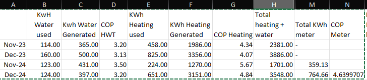
I replaced my 4 pipe 100L buffer tank with a 300L volumiser 2 months ago, along with some re-piping to increase main pipework bore from 22mm copper to 40mm MLC (around 50m, including return). The changes in COP, due to the lower LWT possible and less cycling is clear:
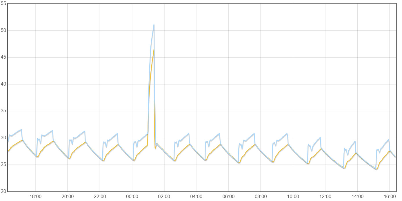
A bit more info. attached is graph showing 24 hours power consumption where you can clearly see the amount of cycling with about 8c outside temp. Temp has to get down to about 1c before it goes into continuous
Recently added a 70l buffer but configured as a 3 pipe system and its certainly helped reduce the cycling and I can now see the HP pump modulate down to 8lpm where before the second fixed speed pump dominated low flows and it cut out at 16lpm. Would like to configure as open loop system again without a buffer but as no one has successfully (?) managed to extract the pulse stream yet from the Samsung to control the second pump I’m waiting for progress to be made or reported before attempting this.
Some drawings of the 3 pipe system show a none return valve in the flow from the HP
I haven’t fitted one…anyone any experience of this?
Since the PWM input to Grundfos pumps is completely passive and isolated, the only limitation on driving both pumps from the same PWM output is the current driving capability of the Samsung PWM output. Either contacting Samsung technical support or someone with a 'scope and a resistor should answer that question. I suspect the Samsung output circuit is pretty simple, a FET in series with a current limiting resistor, the resistor providing protection against inadvertent short circuits during installation.
Thanks for the reply, was thinking on similar lines to extract the pulse by using the samsung pwm to drive a FET to avoid any loading with an opto isolator in the drain but powered by the HP pump + line or similar then extract to control the second pump .
I suspect the HP pump is run on 240v ac with its own power/pwm controller built in to it?
If it’s a Grundfos, then yes. I was thinking of a Samsung Gen 6 where the primary pump is external, so fairly easy to parallel up connections with a secondary pump. If it’s an integrated unit, then maybe warranty/safety considerations become more of a worry, since you will have an obvious modification.
Yes we had a check valve in the flow immediately after the 3-port valve. This was to stop gravity circulation but never saw this happen - probably because we had a check valve. It was useful though when the heat pump was installed as it highlighted that the flow and return were piped the wrong way round at the heat pump. The system worked when it was tested with hot water but the flow stopped when it was run on heating. schematic as follows… 100b heating schematic.pdf (78.3 KB)
When we ran the system as 4 pipe there was a reasonable temperature drop from heat pump flow to heating flow in the order of 2 degC. This went away when we switched to 3 pipe operation. Probably the best way to operate it to avoid vexing the distortion mongers. Presently we are operating it as a volumiser on the return and that has made a bigger difference to overall operation.
In terms of the optimal placement of a Volumiser, this article makes a compelling case for putting it on the Flow side instead of the Return:
While it’s natural to think of a Volumiser as providing a source of warm water for use during defrost cycles, it’s better to treat it as a sink for cold water coming from the heat pump during a defrost cycle - helping to stop the emitters from cooling down so much.
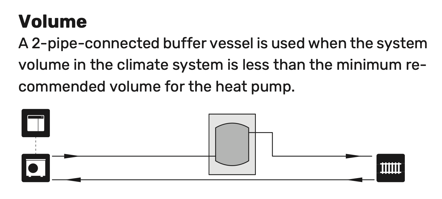
This approach is supported by guidance from trustworthy manufacturers - for example this is an extract from a NIBE installation manual, with the Volumiser clearly on the Flow side:
On our system we had roughly 150 l open system volume and a 150 l buffer. When run as a 3-pipe buffer the temperature difference between the flow from the heat pump and the flow to the system went to almost nothing because we were able match the flow rate on the secondary side with the flow rate on the primary side so there was no draw from the buffer. If the secondary side flow is higher than the primary the difference will be drawn from the buffer which can result in temperature changes. As far as defrosts are concerned we didnt notice any difference probably because we had more than enough open system volume for the buffer not to contribute much.
In the end we stripped the buffer out entirely and replaced it with a 70 l volumiser on the flow.
The added benefit with this arrangement is that when a hot water cycle finishes the temperature of the remaining ‘hot’ heating water in the flow pipework from the heat pump is reduced by the water in the volumiser so the closest underfloor circuit isnt hit with excessively hot water - a consideration if there is a long run from the heat pump to the main 3-port valve.
There is a (minor) defence of placing the volumiser in the return. The RWT is normally a few degC colder than LWT, so heat loss from the volumiser will be slightly lower if it is in the return. The difference may only be 10W or so, but this reduction is applying for the 99%+ of the time that the heat pump isn’t defrosting. I suspect that this may be why the majority of installers voted to install it on the return. [Edit: of course if this heat loss is within the house envelope then it makes no difference, but if it’s into (say) an unheated garage/outbuilding it will.]
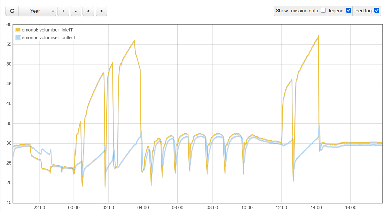
below is a screenshot from earlier in the year showing the volumiser inlet and outlet temps when the external temperature was below freezing. the high inlet temps are during hot water runs between 00:00 and 04:00 and 12:00 and 14:00. the remainder of the time the system was running on heating. i suspect the flow temperatures are high during the hot water periods because the 3-port valve heating outlet is within 450mm of the volumiser inlet so this is likely temperature creep along the pipework which is picked up by the sensor close to the valve outlet but there could also have been a little leakage through the valve. we had an issue with this when the 3-port valve was on heating with low temp heating water being forced through the hot water coil cooling down the cylinder. this has now been fixed by replacing the 3-port valve.
the screenshot also shows some defrost cycles. there is a small difference in reading between flow and return sensors when nothing is running and there are also losses across the volumiser which account for less than 1 degC however the trough temperature at the outlet is higher than the inlet by more than 1 degC. my inference is that the volumiser appears to take out some of the defrost drop. also evident is the flow to heating straight after a hot water run. there is a slight increase in outlet temp however no where near what it would have been if there werent a volumiser in the way.