Glyn hadn’t told me that he sent out any units. That said, I am happy to hear that he has. I was hesitant because it’s a lot more straightforward dealing with someone with a production unit vs the a homebrew device. Not to diminish those efforts, but the approach to problems is easier.
Yes, that is the current version.
This is a tough issue. All data logging is accomplished by reading from the log and posting to the server. That architecture makes possible the wifi/internet failure recovery and uncouples the server posting from data collection. So whatever gets sent to a server must be in the log. As I’ve been trying to get this thing under control and released, I have avoided mission creep, to the point where expanding the log file record is a backward compatibility and conversion issue as much as a technical challenge going forward. Let me process this in the background for a few days.
That concerns phase shifting L1 voltage to L2 and L3. That’s basically what the eMon three phase sketch does, if you like that, you should love this. The gold standard of course is using three VTs which is also supported.
The update server is just loading the update onto a server and downloading the file. There is a php file that you can query to find out what version is current for a patrticular update class, but then IotraWatt just downloads the file as it would any other file. So the update server is just any webserver like apache.
The update blob itself is a different matter. I build that offline in an ESP8266 device that I call my “enigma”. OTA updating is a security nightmare. IotaWatt doesn’t have enough heap to reliably use TLS for secure internet downloads, and a method of authenticating an update is needed anyway. I do that by signing the update blob with a private key that is kept in the EEPROM of my offline enigma signer. The corresponding public key is hard coded into IotaWatt. The OTA update requires that the update blob signature verifies with this public key. Most users will take comfort in this arrangement and my intention to never share the private key with anyone or even expose it to the internet.
So the issue becomes whether I want to become a CA and administrate update certifications beyond what I have already put in place, and will I also need a revocation process as well, and just how far do I want to go in reinventing the wheel?
Before I think about any of that, I’d rather explore the needs of the user base and see if they can be met with mainstream changes in the official releases. It is open, and you can do a pull request.
I wanted to find out what device you had before addressing this. Now that I know, I think the problem is that your device probably doesn’t have a battery yet. Open it up and see if there is one. It takes a CR1220 lithium coin cell. (the screws are under the rubber feet that just pull off).
Spoke an instant too soon. Everything is there and working, but I was just trying it out to be sure on my split phase US system (L2 is 180 degrees from L1). Discovered that I had limited the phase shift specification in the app to 5 degrees. It’s a two line JS change and when I did it and configured an HWCT-004 (1000 turns .5 deg lead) to generic 1000 turns 180.5 degrees lead, it worked fine.
I have another fix for another ALPHA user so I’ll put that together with removal of the phase spec limit and push 02_02_20 to ALPHA update class tonight or tomorrow.
I’m eager to get some experience with this, both to determine the accuracy and to figure out a simpler way to approach the user interface. Im thinking along the lines of specifying that the appropriate three phase (or split phase) shift should be set automatically. Iotawatt can determine the phase shift of a CT from a VT, and round that to the nearest multiple of 120 to get the base three phase reference. Maybe we can try a few different approaches, but that would make deployment pretty simple.
@overeasy: I’m also curious about this! I bought 2 extra VT’s, but i can compare them on the same device. @Simsala: you can get the powerfactor and frequency from the device via http (ip_of_iota/status?inputs=yes&outputs=yes&stats=yes"), so you could log it that way? I’m using this to display it (not logging) on my domotica Rpi-server.
It does work, just not sure how accurate it is. Not a power engineer, but there’s a good OEM Learn section about how varying loads can change the apparent phase angle. So at this point I don’t know if using one phase as a reference for the other two is viable. At best it assumes all three phases have the same voltage. But depending on the accuracy required, it may be a good choice for a lot of three-phase. At this point I just don’t know. The OEM “three-phase-sketch” attempts to do this, and @Simsala says he has a new improved version, so I guess it’s working already for some folks with the TX. If it’s not up to snuff for a particular user, the three VT solution should be. You can try it both ways. That will be a good test. You should be able to do both at the same time on a single IotaWatt.
Yea, that’s one way to do it. You’ve been reading the code. But there are some caveats:
The status display values are damped, so they are not the same as logged values.
That method will only work in real time, whereas logging that data to the SD card and posting to a configured server will save insure against data loss in the case of internet disruptions.
The data is produced, but the devil is in the details. How to add it to the log without doubling the requirement for everyone, and how to put it into the user interface without needlessly complicating it for most folks who couldn’t care less.
I have some ideas, but it needs to simmer for awhile. It involves a separate auxiliary log, possibly at a longer posting interval. Most of the internals to support the current log are implemented in a class for which another instance can be created. Stay tuned…
I was thinking the same, that would make deployment indeed a lot easier!
The battery was there, but it was a cold solder joint of one pin of the battery holder. I did solder it, it seems to be working. Now, only the first entry after reboot has no time stamp “No clock yet: SD initialized.”
Thanks for the hint, and good too know that I’m not the only one interested in these values!
Sorry about that. Not the first one I’ve had. That particular one has been a problem because the battery holder itself is a huge heatsink. I needed to crank up my iron to fix the last one. I’ve started using a higher reflow temperature in my toaster-oven, but the manufactured boards should not have that problem.
It’s normal for the first line to have no timestamp.
@overeasy: i was going through the code and was wondering what the difference between ADC_BITS 12 in IotaWatt.ino and _ADCbits = 12 in IotaInputChannel.h is? They both define the same ADC (MCP3208) i guess?
I don’t remember offhand. There’s a lot of baggage in there from the various stages of developing this. At one time, I entertained the notion of using MCP3008’s (10 bit) but when I saw the stunning increase in accuracy, I went all in on the 3208.
Right now I’m in the middle of converting the source to work with platformio. As time allows I’ll be cleaning up some of the detritus from efforts past.
What I did notice: The device name as shown by my router is still shown as “ESP-238CA3”. The emonESP is listed as “emonesp”, which is quite nice and makes it easier to find. Didn’t try it but I think it’s the hostname declaration EmonESP/src/wifi.cpp at master · openenergymonitor/EmonESP · GitHub
@overeasy: just to be clear: to measure something connected to Phase2 using a VT connected to Phase 1 i should increase the phases number in the config.txt by 120? (on a 3 phase setup).
I tried this on an input i had running, but it seems that the measurements are a bit off…(still running 2.02.15)
it says 44 W where it should be around 100. (using the vt on phase 1 and adding 120 for phase 2)
it says 3 W where it should be around 53 (using the vt on phase 1 and adding 240 for phase 3)
I restarted the iotaWatt after changing the config.
Jan, I’m getting lost in the weeds with your description. I don’t really know what the relative phase differences are between your phase 1, 2, 3. Try playing around with this tool and see whare it leads you:
What you will get back is the relative phase difference (unadjusted for the phaselead in the VT or CT) between the CT=n and channel 0. You can add the refchan argument to use channel r instead of 0 for the reference.
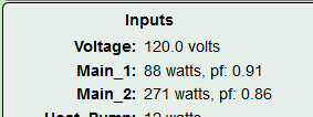
At first, you may be taken aback by the results, but expect the power factor to be in there. For instance on my home, measuring the phase difference of one of my mains:
I get
If I take the aCos of power factor .91 I get 24.5 degrees.
The phase lead of the VT and the CT employed here is approximately the same, so within 1 degree, not too bad.
Play with that and see where it takes you.
You will notice that this is measured with the main at 88 watts. That’s less than one amp on a SCT019 CT with 6000 turns and a range of 250A. Not too bad, but the phase shift at that low current will be high.
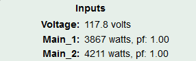
So I turned on the oven and dryer:
Nice. PF 1.00. Now when I measure I get Calculated shift: 0.70
That’s about as good as it gets and would be a PF of .99992537, not that the IotaWatt is that accurate.
Version 02_02_20 now current for ALPHA update class.
Fixes problem with GET/feed/data
Allows specification of large phase lead in app
sets WiFi hostname to device name
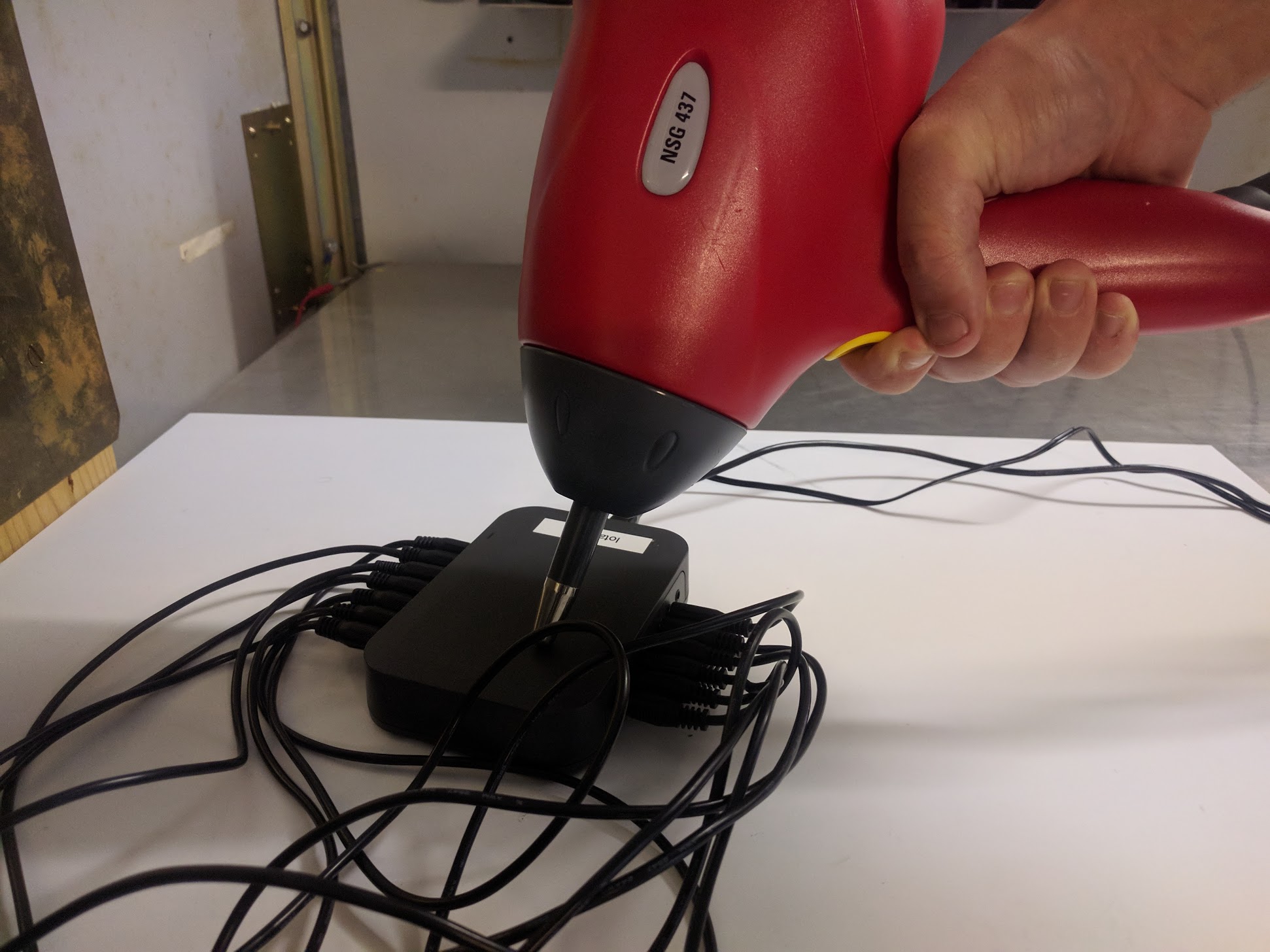
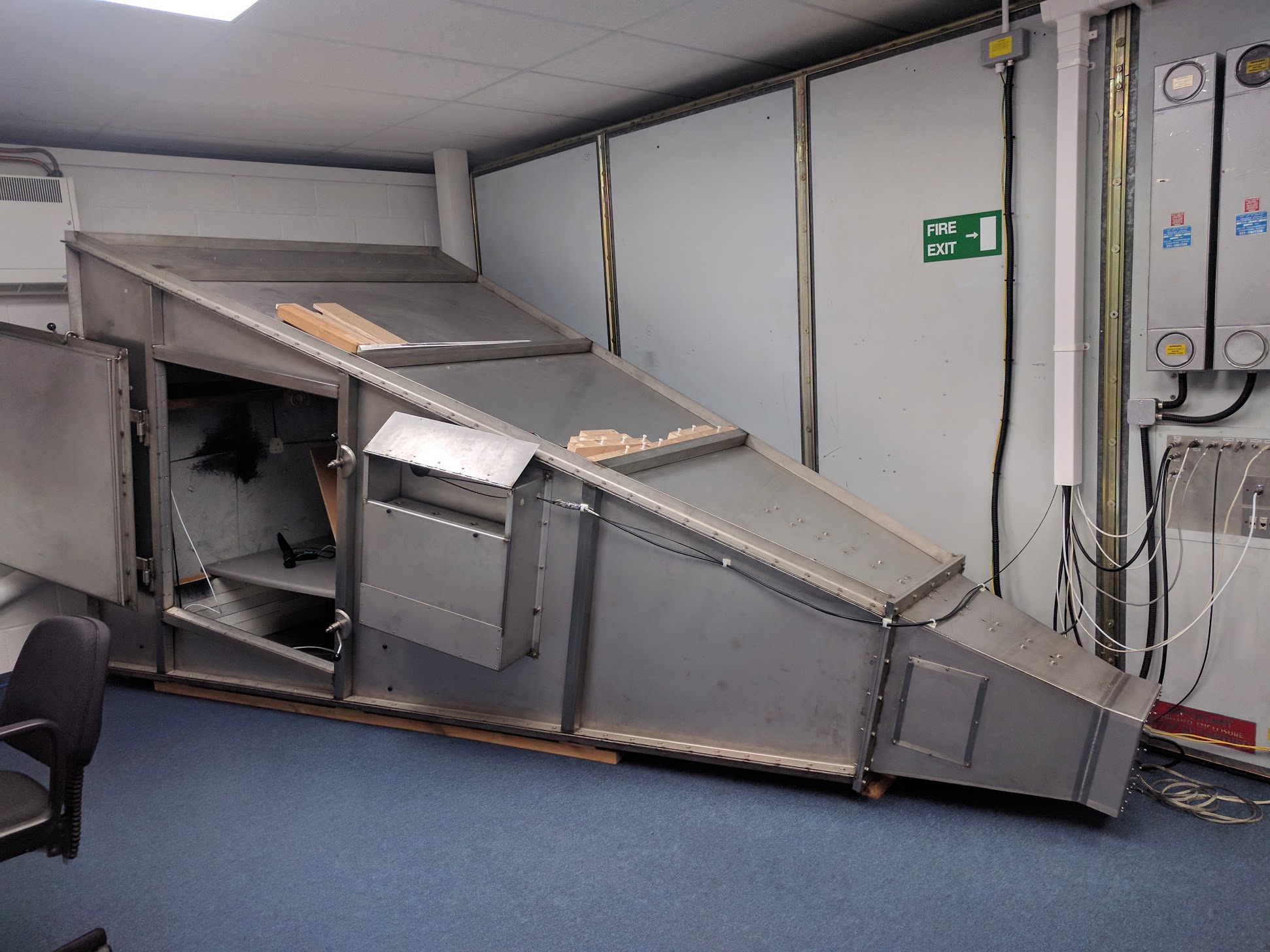
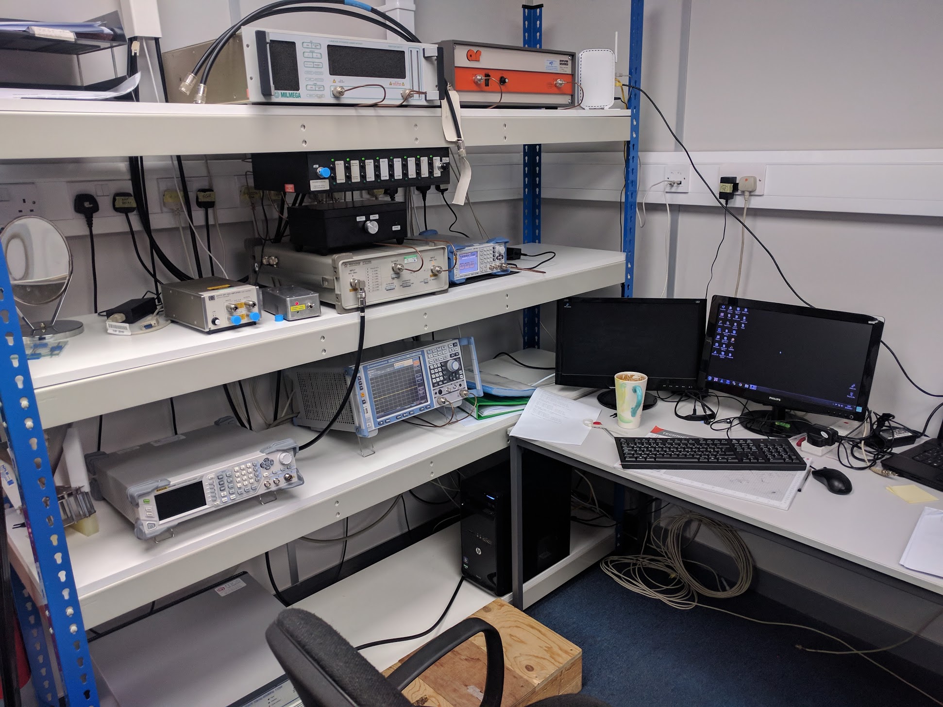
I’m pleased to report that the IotaWatt passed EMC testing for CE approval last week. Here are some photos of the test lab. We used Cass EMC who are great and really know their stuff.
The IotaWatt was tested to the following standards the meet the EMC RED directive:
EN 301 489-3 Emissions and Immunity Standard: Equipment with a Radio Transceiver EN 301 489-1 Emissions and Immunity Standard: Equipment with a Radio Transceiver
The following tests shall be carried out:
CISPR 32 Conducted Emissions – AC Mains input port via supplied PSU CISPR 32 Radiated Emissions – Enclosure port (30 MHz to 6 GHz) EN 61000-4-3 Radiated RF Immunity – Enclosure port (80 MHz to 6 GHz) EN 61000-4-6 Conducted RF Immunity – AC Mains input port EN 61000-4-4 Fast Transient Bursts – AC Mains input port EN 61000-4-11 Voltage Dips – AC Mains input port EN 61000-4-5 Voltage Surges – AC Mains input port EN 61000-4-2 Electrostatic Discharge – Enclosure port
@overeasy: in the code there is a variable for a reversed CT. I read that this can be “solved” by adding 180° to the phase.
However, wouldn’t it be easier to add a checkbox to the config page to set it reversed?
Adding (off course with a , on the line before)
“reversed” = 1
or “reversed” = true
to the config.txt seems not to work?
I guess that i’m missing something
PS: i know that a normal ct will be automatically reversed, but when it can be negative (signed = true) that this will not happen.
There is a checkbox in the config app to say if a CT is signed:
Right. If a CT samples at negative power, IotaWatt will treat it as the typical case of a reversed CT, and make it positive automatically, . The exception is a CT that has been designated as signed, which would typically be something like a Main where there is a PV system that will produce a legitimate negative power flow.
So no need for a checkbox to say it’s reversed, the correction is automatic. The reason for the boolean variable “_reversed” in the code is so the app can make the power value red to indicate that the automatic correction is taking place.
I think I had made the comments about phase shifting the CT specification in a context of demonstrating that the phase correction algorithm can artificially create, or correct, even a 180 degree shift.
I understand, but, in the case one would have installed the CT reversed (by mistake or because it could not fit otherwise) on an input that is signed, the measurements would be inversed, the only solution now is to turn the ct around. In my case i have a few ct’s that are difficult to reach, so i thought that this option could be usefull.
I understand, and I’ve been told that people want to modify and embellish these products to their liking, and that’s fine. That’s what the homebrew category is for. The philosophy behind IotaWatt is a simple solution to whole house energy monitoring, so my mission is to keep it simple. I know it’s going to ruffle feathers when I buck the conventions of being all things to all people.
I used to race sailboats. I would watch others get a new boat and immediately put all kinds of cleats and controls to serve every conceivable situation. Then I would go to a big regatta and see the pros arrive with their stock out of the box boat and do fine. I learned to sail mine for awhile before making changes. I usually ended up with one of those simple stock boats.
There are no less than three solutions to your problem already: