For an SPI CS pin it has to be dedicated output. My understanding is that GPIO 9 & 10 are also data pins for the flash memory, which is active all the time. I tried to use 10 awhile ago and ran into trouble. Don’t know if there’s a GPIO capability for the ADC pin.
I had worked out a scheme to be able to address an unlimited number of SPI devices virtually using the SPI GPIO expansion chip and some binary decoders. Basically you use one GPIO to CS the expansion chip, and using outputs from that (16 pin) chip, set the state of the decoder to direct two other ESP pins to specific SPI slaves. It’s just a handful of chips and would allow the high speed chip select needed for IotaWatt sample rates of more than 14 channels.
I stopped thinking about it back when things were moving more toward the ESP32. I might possibly build a prototype board with the hardware to do it as a proof of concept. It’s less than half a dozen relatively inexpensive chips and I think there’s room.
I agree in general with this, my reasoning wasn’t about price but that I have a single power socket in the meter box and don’t really want to use adapters and multiple supplies. More about the look of the final product than the price. Plus it is fun to try and do some part of this project myself
Do you know of any resources describing these “electrical issues” a bit more?
I am trying to understand it, looking around and haven’t found anything that would describe what the problem is yet. The only thing I am thinking is there may be some kind of “feedback” created with the BIAS and the AC input through the voltage regulator+rectifier, though a friend of mine that does a bit of electronic work suggested it should be possible.
Yeah that is the plan, I don’t need intensity just on/off. I haven’t looked at the code yet, but I think I should be fine with making changes to it to handle this.
Just realized I should probably use I2C instead of SPI, you already have a I2C bus in the design, it is probably perfect for this.
This looks amazing! I still want to try the pulse counting for gas usage (right next to electrical meter box too) and might as well do the light pulse counting anyway.
I think my next step is to order the parts and get a breadboard going.
Thanks again. I really appreciate what you have done on this.
The problem that I see is that the AC reference voltage is +/- with respect to the ground of any DC power supply that you would create from that same AC voltage. so I don’t know of any way to add the AC and DC to get a the biased undulating DC input needed for the ADC. Don’t you have power strips there?
The real limit to the current you can draw is the effective impedance of the transformer, because it’s the component that distorts the voltage waveform.
There’s not a lot of iron in those transformers and the wave shape will be distorted because of that too.
Even a transformer with two secondary windings doesn’t help much - the variable loading of the DC supply portion affects the magnitude and shape of the voltage waveform, effectively putting a “dent” in it.
OK folks, this is a thread about IotaWatt. There’s another thread called Homebrew Iotawatt issues for those intrepid hobbyists that want to build their own IotaWatt hardware. I’m happy to answer any technical questions as best I can there, and good luck to all. Most of the questions are reruns of issues that I have worked and experimented with. I believe IotaWatt represents the most practical solutions to most of them.
IotaWatt 4.0 is a tested production unit that is being manufactured and will be available soon. It does not use the AC supply for reference, primarily for the reason stated above in my last post.
By way of update on the production effort for IotaWatt:
Prototype units are waiting CE testing.
An initial run of devices is in manufacturing, due out in a few weeks.
Firmware in the pipe and working prototype includes a new secure protocol for posting data to Emoncms and an OTA update system with digitally signed firmware and app updates.
Have several ongoing efforts in place to develop proof of concept installations for three phase capability.
Sorry for he delay. I had asked the OEM folks to respond to this, but they have not. At this point, I have very little in the way of information about their plans to resell IotaWatt. I am looking into alternatives and will probably have some boxes available in a month or so. I’ll PM you when I have more information.
Hi Bob, I’ve been following your development of IotaWatt and would like to set one up at my location in New York when they become available. Let me know when they are ready and how much you need for one.
Thanks much,
I currently have emonTx Arduino shields monitoring individual circuits in residential applications to identify high use branches. Other projects include monitoring heat pump water heaters and ground and air source heat pumps. Since the emonTx’s are limited to 4 CT’s each and I have to modify the burden resistors depending on the size of the current draw on each line the IotaWatts capability to handle more inputs and modify the burden resistor through software would make life a lot easier.
So it sounds like you are in the business of energy auditing. IotaWatt should make your life easier.
IotaWatt has 24 ohm burden resistors on all of the current channels (0.5%). With the ADC reference voltage at .2% and high sample rate 12 bit ADCs, you will not have to change the burden resistors to get accurate results.
That might be the case regarding wear levelling but have you considered basic SD card corruption?
I know SD cards offer a very low cost storage solution but certainly my experience is that it’s not a system that can be relied upon.
Have you considered SPIFFS?
Have you considered an internet only solution i.e. internet is inherently reliable and for the odd occasion it’s down simply forgo energy monitoring. For me I would be more concerned about the internet being down than knowing how much energy I had consumed, and associated cost, during the outage.
can you point us to some data that demonstrates the probability and/or severity of this? SDcards have become ubiquitous. Anecdotally my experience is just the opposite of yours - it seems to be very reliable in this application and everywhere I use them. Virtually all of the SDcard problems I’ve encountered were of my own doing in misusing the FAT file system layer that is between the code and the physical card.
My understanding is that SPIFFS is the same technology as the SD card. Also, it wouldn’t hold a day’s worth of data.
I’m not sure what problem that solves in the context of these questions. IotaWatt does log to the internet, in fact it currently supports two different time series database servers. (Emoncms and influxDB). Support will also be added soon for MQTT which will be a generic bridge to a variety of other data servers. What would be the advantage of removing the local SDcard storage capability?
I guess I don’t know what aspect of the internet makes it inherently reliable. In the context of this question, the internet is: the local WiFi router; the ISP; the internet backbone; The server’s ISP; the server itself; and the server application that I connect to; That’s a lot of moving parts. IMO an SPI link to a local SDcard looks pretty good.
I haven’t had any IotaWatt installations report SDcard failure. On the other hand, there are hundreds of cases where one of those links (usually the local router) failed for some length of time and the data was subsequently automatically batch uploaded from - you guessed it - the SDcard.
thanks for your constant and professional work at the IoTaWatt device. It’s great what you achieved with only the ESP. I’m currently testing it, here are some first impressions:
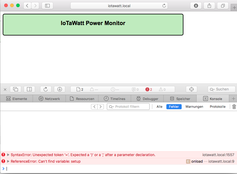
it’s not working with Safari browser, here is a screenshot:
Elias,
Can you give me some context on this post? Where did you get your IotaWatt and what firmware are you running?
I wasn’t aware of that Safari incompatibility. It has always run fine on my Ipad Safari browser. I’ll have to look into it. Offhand I believe that is the only place I use a default parameter value.
I elected to run graph, the message log, and the editor as a new page rather than mess with frames. Browser back button does the job.
You can’t. It’s only available on the status screen. Keeping that stuff in the datalog is a huge increase in storage requirement and I’ve had very little interest in that data historically.
Best part is that with low tolerance components, it’s usually pretty good without calibration when using a standard VT.
It should work right now. There are two ways to do it:
You can add two more VTs to get voltage and phase reference for each leg. I plan to make some adapters to allow connecting a standard issue VT to any of the power channels. If you want to do it yourself it involves changing the 5.5mm barrel connector to a 3.5mm stereo jack and adding a 288ohm (or the next higher available) 1/2Watt resistor in series. After that, you configure (and calibrate) the new VTs, you will have the option of specifying the VT that corresponds to each power channel. You can customize outputs to display and Emoncms to add together the various legs of a three phase device (or mains).
Another way is to just use the generic CT specification on L2 and L3 and add 120 and 240 degrees to the phase lead respectively. That probably won’t be as accurate as the three VT method, but might serve your need fine.
sure here is the context: I work with a few people in a project in germany with quite similiar goals like the openenergymonitor project. We help people to understand what energy is and how they can use it more efficiently. In order to “make the energy flow” visible we are using mostly emontx. In germany it’s common to have a three phase supply so we use the three phase firmware for that (which by the way was improved grandiosely by Robert W. in the last few weeks). We got a sample IoTaWatt with our last order for evaluation/testing purpose.
I’m on the alpha update channel, so the current version is 02_02_19.
We are involved in some scientific project, where powerfactor, current and frequency is interesting and important too. So having the opportunity to log theses values too, would improve it a lot for us. On the other hand we usally don’t need 14 channels for power.
Sounds plausible, I will have a try with that.
By the way: Are you going to publish and document the update server part as well? That would enable me to have some IotaWatt in a specific project with a customized firmware and still use the auto update feature.