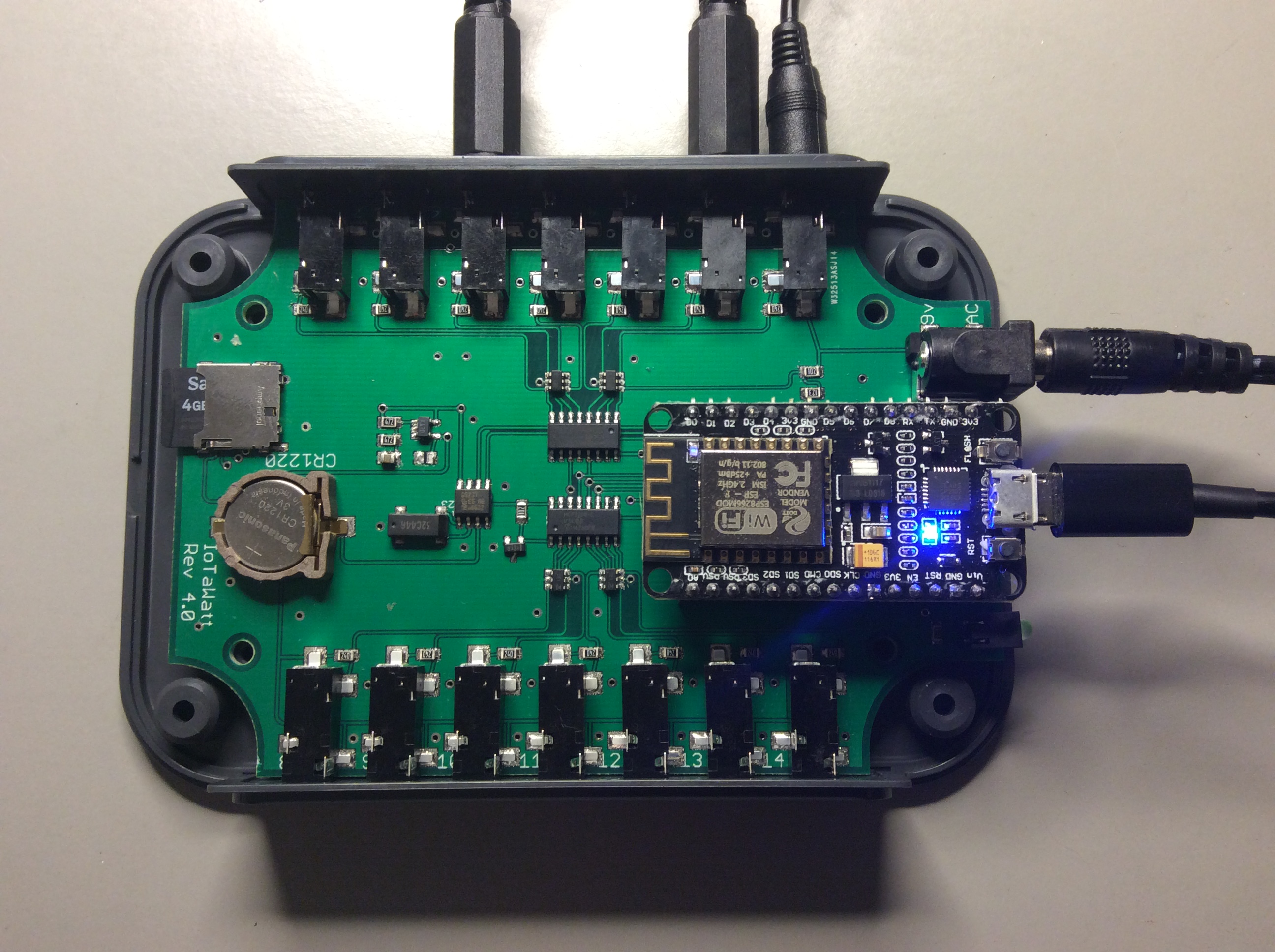
The latest IotaWatt, now with OpAmp bias circuit and TVS diode arrays protecting all the inputs. Ready for CE testing. Component count has been cut in half and stability seems to be improved.
Just keeps gettin’ better n’ better.
Looks Great! Better than some commercially available units I’ve seen.
This looks impressive!
I couldn’t find any details of what is in this particular version on Github. Also I think you should include the link to Github on any posts relating to this.
Is this expected to cost more or less EmonTX V3.4?
I am concerned about the placement of the ESP8266 for two reasons.
- They generate a fair bit of heat, which might cause drift in performance of some components.
- The RF output does cause some interference and RF induced heating in other components.
I think the antenna should be placed towards the outside of case. Alternatively an ESP8266 module with an external antenna could be used. Might be over kill.
Have you tested the accuracy operating in ambient temperatures up 50C?
These would likely be installed in garages or power boxes where the temperature could easily be above 40C.
That looks like a NodeMCU. The quality of the voltage regulator circuits on these seems to be highly variable. I have found some of the poorer quality ones have even cause errors (spikes) in the reading from digital sensors like BME280. I would have thought it would have been very difficult, but it does happen and not just limited to unit or design.
I highly recommend using Samsung micro SD cards, particularly the EVO series for this sort of application as they have some wear leveling. Just wondering if the write frequency should be a user variable or at least made easy to modify in the script?
Just wondering if you considered using the audio (3.5mm) connectors like those found on a motherboard?
Three high by two wide.
The ESP8266 probably still has capacity to have an i2c connection to allow the easy connection of a temperature, humidity and pressure sensor, like the BME280, externally to the unit.
Thanks for the feedback. A lot of these are design issues that could be revisited in the future if they become issues, but it has been a long road and the current emphasis is on getting the required approvals to bring this to market. Regulatory testing is expensive and any changes require retesting. That said, I’ll try to address some of the issues that you raise.
I think the firmware is pretty current. The schematics and board may still be the V2 feather version, but I will put the schematic up soon but will probably not maintain a PCB layout on Github.
Whether or not OEM decides to sell this device and the price would be a question for the principals. I am not part of that organization.
The placement doesn’t seem to be a problem. Heating, either of the ESP8266 itself or any induced heating has not generated any problems or concerns. In the latest version, the nodeMCU is about 15mm off the main board on headers and the volume of the enclosure has been doubled, which should allow for RF separation and any heat dissipation.
WiFi seems to work fine with the onboard antenna. Trust me on this, going to an external antenna would increase the regulatory approval cost by an order of magnitude.
No.
Have had the opposite experience, maybe because I stick with one particular brand. There are a lot of sources of power problems. I think the quality of the 5V USB supply is probably more of a factor than the nodeMCU regulator. IotaWatt has a pretty accurate (and temperature stable) onboard voltage reference shunt. So drift of the nodeMCU 3.3V regulator is compensated. The IotaWatt is probably better protected against spikes than the nodeMCU itself. In any event, this has not been a problem. Typical test units run for weeks in real environments.
Wear is not expected to be an issue with the SD cards. 99% of the blocks will be written only twice over a ten year life. Even the cheapest cards have adequate wear leveling for the handful of volatile blocks that will be written, and the failure mode for those blocks is not catastrophic.
No. The current form factor has plenty of room.
Actually, the ESP8266 doesn’t have a lot of I/O pins, but I do use I2C for the real time clock, so a hacker could jump on those pins with a different I2C address and talk to another device. That said, most folks like the DS18B one-wire temp sensor, and there are no pins available to add one-wire.
One of the reasons I like this space for the IotaWatt is that the devices are open and people are not shy about hacking the various devices for their purposes. When this device becomes available and is reasonably settled down, I will probably publish something like a “Hack my IotaWatt” thread to that audience. In the meantime, I’m keeping my head down and trying to avoid those distractions in the interest of getting the base device done and generally available.
Regards.
Looking very nice!! Can’t wait to get my hands on one!
Any idea when and how we can buy one? (or do you sell them?)
Yes, I realise I am very late to the party on feedback. Sorry about that.
Looking at the picture again, I can see that now. This is good.[quote=“overeasy, post:1, topic:4427”]
Ready for CE testing.
[/quote]
I am a little confused about the need for testing/certification. Are you going to sell them as finished units or just make the designs available?
I think this is why you haven’t seen problems. I have one brand/supply of NodeMCU that is really good. Two others have been problematic. I too had assume that it was a power supply issue. A poor power supply can contribute to the problem with these NodeMCU, but the problems still occur even with good power supplies on the NodeMCU that suffer from these error spikes.
Working on both.
Could you tell me what kind of tvs you used? The schematic on github didn’t specify the type.
I am also a bit confused: there is 1 vt connector (next to the nodeMCU) but the firmware lets you specify the inputs as CT or VT. Can one just connect a VT to one of the stereojacks (so i can connect 3 VT, one for each phase of my 3phase system?)
(sorry for my noob questions)
D3V3F4U6S-7
You will need to remove the burden resistors on the two additional voltage channels, and present the AC reference signal using an attenuation circuit consisting of a 10uf capacitor in series with a 12K resistor and a 1K resistor. Input the voltage across the 1K resistor to the IotaWatt channel.
If you stare at it for awhile, you will see that replicates what is in the dedicated voltage input.
There are other ways to do it as well:
Replace the burden resistor with a 1K (0805) resistor and connect the VT leads with a 10uf capacitor and 12K resistor in series.
Lastly, don’t remove the burden resistor and connect the VT leads with a 10uf capacitor and a 288ohm resistor (or some close standard value like 270 or 330). This method will draw about 40ma and dissipate about 40mw of heat from the burden resistor, but if you just want to experiment it should work OK.
You will need to calibrate those VT channels as described in the GitHub WiKi.
Thanks for the clarification, i’ll change 2 inputs to look like the dedicated voltage input.
Is this type critical? My online shop (conrad) isn’t carrying them, and mouser/rs is charing quite a shipping cost. I suppose it has to be a 3.3V vrwm, but any other specifics needed?
I get them from digikey. Their shipping via usps (USA) is very reasonable. Probably around $3 for just say 10 of these and 3 days. That said, you can actually leave them off entirely and the thing will still work, just no additional ESD protection beyond the nominal provided in the ADCs. Using these arrays instead of simple TVS diodes provides some “rail to rail” protection against overvoltage from the VTs and CTs.
Other manufacturers make sot-23-6 diode arrays that should substitute just fine. I just looked up ON semiconductor CM 1224 which looks fine in the 3.3v version.
Thinking about this after I responded to your last inquiry, I have not actually tried any of this, although I have high confidence it will work. I’ll give it a shot over the next few days. The idea of leaving the 24 ohm burdens in place and using an external 300ohm voltage divider resistor seems better to me now that I’ve thought about it. From the perspective of power dissipated through the 24 ohm resistor, it’s the same whether you are using it with a CT or a VT in this configuration.
The capacitor is really not necessary either in the normal case, I’ve just always used one there. Initially I put one in because it’s common to find D.C. Wall supplies that have the same 5.5mm plug, and I wanted to protect against accidental use of one. That’s probably not a catastrophic problem anyway as the D.C. (iOS wants the periods) would need to be more than 12 volts to overvoltage the ADC.
So it looks like it should work ok plugging the VT right into the 24 ohm burdened channel using about a 300 ohm resistor in series. Simple enough. I’ll try that out over the next few days and get back.
That was easy. I soldered a 3.5mm jack on a VT with a 330 ohm resistor in series:
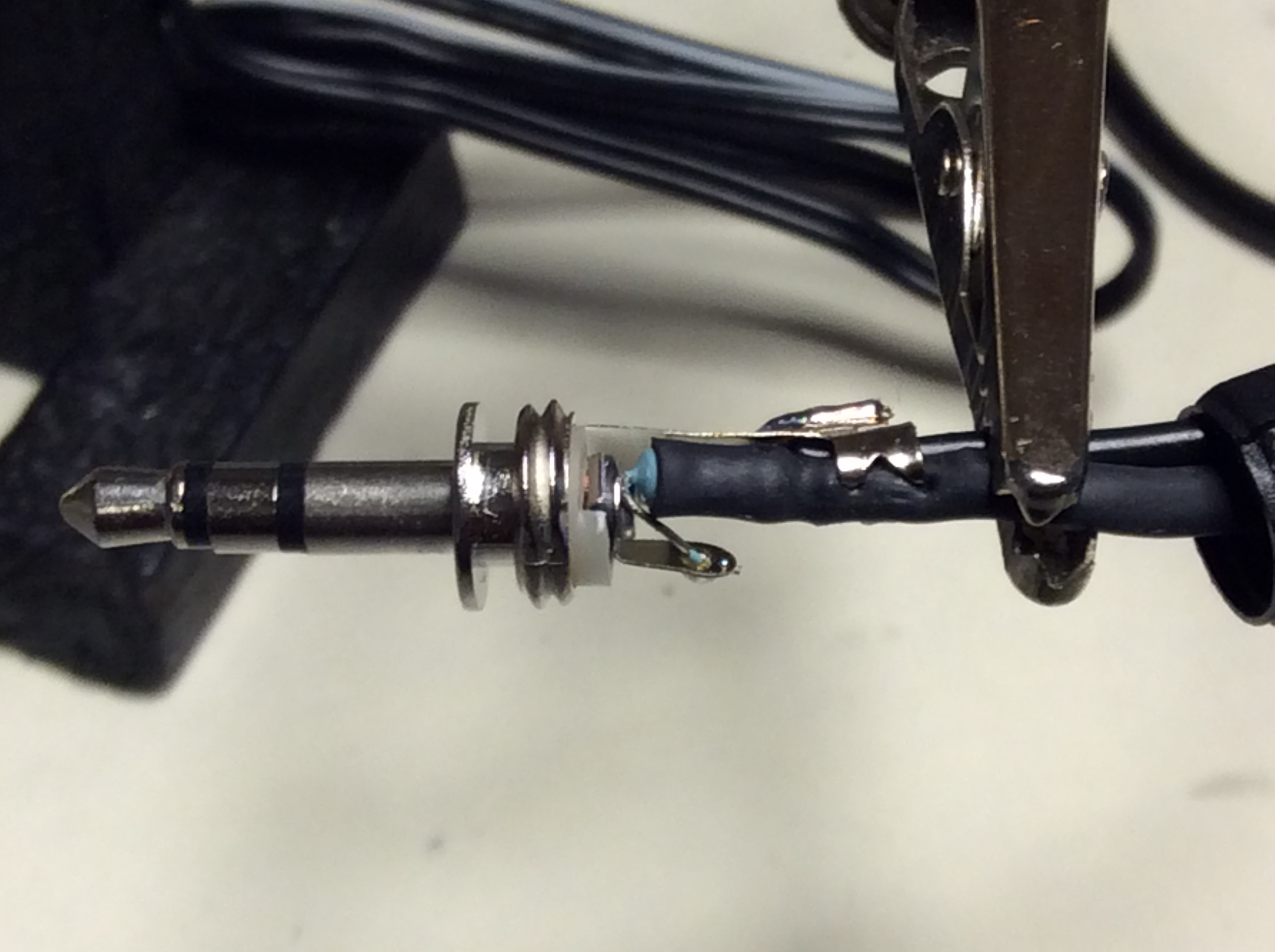
Plugged it into an IotaWatt input and configured it as a VT. Calibrated it as per the WiKi instructions, and ran it for awhile. Here is a graph of the standard VT input and this additional VT on channel 1:
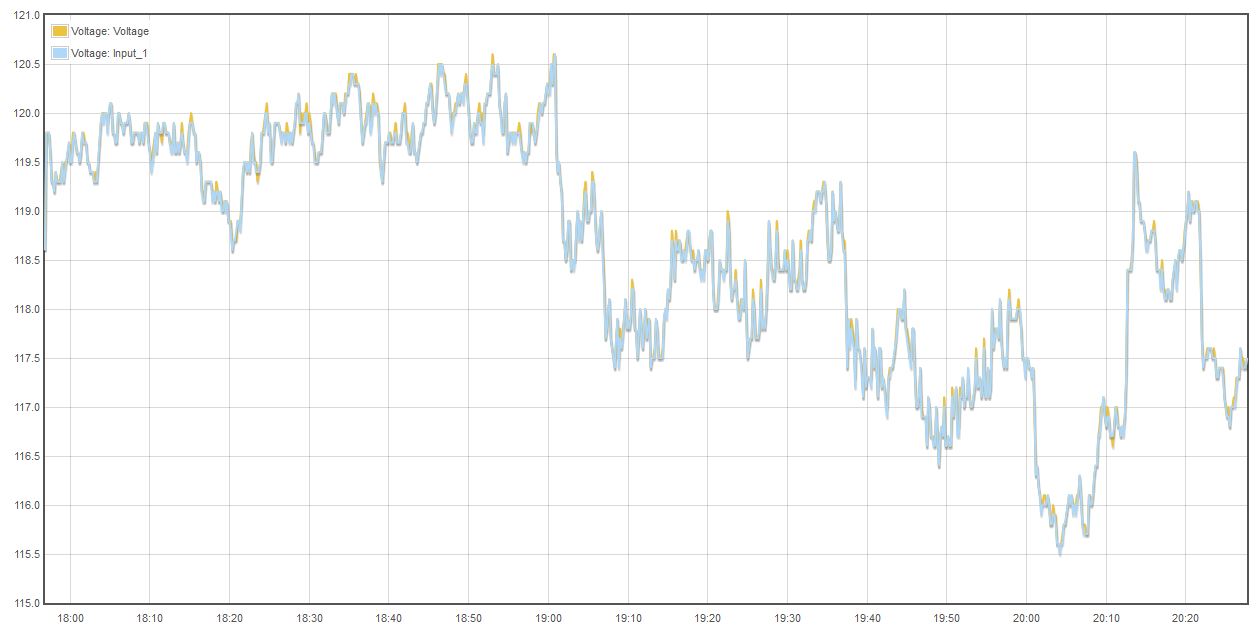
So that’s all there is to connecting and configuring another VT. Once an additional VT is configured, there will be a selection box listing all of the VTs when configuring a CT.
Looks great! Perfectly aligned!
In a few weeks i’ll give it a try, I ordered the components and the board (slightly adapted to minimize the number of smd since i do not have much experience soldering them) from dirtypcb.
I will try it first without the tvs (they charge 20€ shipping to Belgium…)
Maybe i should have waited till your response, but i changed the input 1 and 2 (adc 11 and 12) to the schematic for the VT.
Looking forward to “playing” with it 
Maybe a stupid question, but how do the inputs on the webpage relate to the adc’s? 0 is the dedicated VT (thats ADC10), so i was unsure if the nrs on the pcb are the nrs on the webpage.
Sounds like you have everything under control.
Its not a stupid question, but it is something that you should come up to speed on if you intend to build and troubleshoot a unique implementation of IotaWatt. I think you will find that taking the time to understand the overall structure of the program will save you a lot of time down the road.
With regard to this particular question, the latest schematic on github has the inputs labeled J1 - J14 and they have corresponding ADC input nets. The firmware currently on Github configures the inputs that way in the default case, but any override mapping can be specified in the json config file.
Happy prototyping.
When i get back from holyday i’ll get up to speed on the firmware! (been looking a bit into it but luggage duty for my wife is more important )
On your reply: in the schematic (4.1) the J1 to J7 is connected to ADC11-ADC17 and J8 to J14 is connected to ADC1-ADC7 (thats why i was a bit confused), but when looking into getconfig i saw that you switched the mcp3208’s
When looking through te code i was wondering: greenLed is defined as 0 , isn’t this giving any problems with the ADC on the same pin? (or is it multicolor led?)
That’s probably a good idea. Using the 24 ohm burden and a 330 ohm voltage divider the 24 ohm burden dissipates about 27mw of power, which is fine for that SMD resistor on the open board, but the 330 ohm voltage divider gets the lions share of it and dissipates about 380mw. In that closed connector, it heats it up enough to feel it:

You can make out the 3.5mm jack - that’s the one that’s marked 100F. You can also the nodeMCU. The cool square (blueish) is the actual shielded ESP8266. The bright spot to the right is the voltage regulator. That gets a bit warm as well.
So for a permanent install, I’d recommending getting larger resistors for the voltage divide, even if it means replacing or removing the internal burden resistor.
Awesome, can you give us hint on the pricing?
I’m afraid not yet. Final manufacturing details have yet to be finalised. Too early for pricing, I would be making up figures if I tried to give you an indication at this point. Very sorry.
Pricing may change between this first pre-production run (50-100 PCS) and the final production units.
I’ll let you know pricing as soon as I can.
I really like what you are doing. So smart to embed a Feather w/ WiFi. Is it possible to share the schematic and BoM? I’m interested in morphing it to have 20 CTs and use a Feather M0 RFM69 instead of the ESP826 (then RFM69 to a “base station”).
Well done.