Incompetent Installers , incompetent regulation Do I need a MIM-B19N?

Hi Trystan,

Many thanks for the information about Heat Meters!.

Today , my losses , presented as a percentage are

02121054

I emphasise again, these are estimates with the Drop in Temperature between the Heat Pump output and the Indoor unit contributing a further 6.5 C to the losses.

Again, The Real COP is the Heat Pump COP x Heat _Exchanger Efficiency

REAL Efficiency = 3.5 X 0.85 = 2.9

I emphasise, again, the Real Efficiency of my Heat Pump is even less than 2.9 given that I have neglected the temperature drops across the SIKA Water Flow sensor .

My Temperature meter shows the drop across the Water Flow sensor and pipes is 6.5 C.

!!! HOW DO I FIX THIS HEAT PUMP !!!

What can I do to improve the real efficiency ?

Do I replace both motors with motors having a power of 120 Watts ?

Can I remove the Heat Exchanger completely?

ian

Hi TRystan,

Sorry , I sent the wrong Graph , again.

MY percentage drop across the Indoor unit is

loss_02121054

When the drop across the SIKA water flow sensor is added the efficiency drops to 75%.

I know all the caveats , about my assumptions and measurements, but , What do I do?

The Heat Pump Real efficiency ~ 260 % , or 2.6 .

From my Electricity bills I have estimated the Real efficiency as ~2.6 .

ian

Ian,

I have looked back over my history to find an instance where heating DHW caused a defrost. I found one on the morning of 18th January.

DHW Heating started from the schedule at 03.00.
The defrost started just before 03.20. On the graph you can see that the cylinder return, heatpump return and DHW tank bottom reduced in temperature while heating return was unaffected. The defrost therefore used water from the hot water circuit.
The DHW restarted and continued to 03.30 when the schedule switched it off.
At about 03.34, the heating came on and at 04:15 a second defrost occurred. On the graph you can see that during this cycle, both the heatpump return and heating return reduced in temperature while tank bottom and cylinder return were unaffected. This defrost therefore used water from the heating circuit.

As a result of this I can be extremely confident that my Samsung simply uses the active circuit for the defrost cycle. This makes sense because it knows there must be heat in that circuit.
I have looked in the field settings and nowhere can I see any option to specify the source of hot water for the defrost cycle.

I therefore think that your statement about using hot water for defrosting is incorrect and you have been heating your hot water unnecessarily and causing more defrosts using DHW as a result.

Christian.

Edited for typo.

Hi Christian,
Many thanks.

Yes, you are correct , I had previously switched the Hot Water Heating OFF the previous evening.

01311020

At 8 am on the morning of the first of February the Heat Pump was displaying an flow water temperature of 65 C!.

This could not be a call to the Hot Water system , given that it was switched OFF.

Being unable to safely reduce the very high Flow Water Temperature , I switched the Heat Pump power OFF.

Taking readings from the Temperature files themselves , I found that the incident consumed about 3.5 Kwh of energy.

This kind of thermal runaway has been noticed before, with one incident being shown to my “installer” who promptly disappeared out of my front door.

The Heat Pump should not have gone into thermal runaway.

My other recorded incident revealed an identical consumption of 3.5 Kwh between 4 am and 8 am .

This second incident could have been caused, as you say, by the Hot Water System starting at 4 am .

I have no other recorded incidents of the Hot water system starting during the night.

Many thanks for your evidence ,

ian

Hi Christian , Trystan,

On talking to Joule about my problems with the Heat Exchanger , i received some documentation Heat Pump testing where Heat Exchangers are used.

All of the measurements that Joule take are identical to my own eventual measurements.

My “Installer” has never performed these tests on the Heat Exchanger.!

A Heat Exchanger does result in 3 C #temperature drop that is not recorded by the Samsung Heat Pump itself.

I have a further drop of 6.5 C between the Heat Pump output port and the Indoor Entry port of the Indoor unit.

The Total drop is therefore 10 C , representing a (10/42) x 100 = 24 % drop that is not recorded by the Samsung Heat Pump.

The Heat pump was “designed” by my “installer” for a Water Flow temperature of 35 to 45 C.

With a Temperature drop of 10 C the heat pump would have to supply water at 45 to 55 C, which would be totally uneconomic. The Unit is already consuming 150% more energy than it should!

A second revelation comes from another document from Joule.

This document again confirms that my Weather compensation is working perfectly.

Also the comments on "running your machine efficiently are very accurate and pointed.

ian

That sounds in line with the calculation I made here: Heat pump & heat exchanger calculator

Im confused where that is coming from? is there not just a run of pipe between those two points?

Hi Trystan ,

The Drop in Temperature experienced between the Heat Pump output port and the Indoor unit input is indeed the result of the drop across the 28mm pipe work.

This pipe work has been “repaired” on at least 4 occasions, representing some twelve pipe “repairs” when migrating both the Water Flow meter and the inline Filter.

The 28mm pipes also have about 12 right angle bends going between the Heat Pump and the Indoor unit.

My Electricity bill has increased by 319 % between Dec 21 and Dec 22 !
**BUT **
**My Electricity rates have only gone up 175 % between Dec 21 and Dec 22 **

This excessive consumption MUST be caused by the Real efficiency of Samsung Heat Hump system as a whole

The inefficiency of the Heat Pump does not correlate with the COP of the Heat pump itself.

The Real efficiency must consider the losses across Heat Exchanger and the pipe work.

At the end of the day the amount of heat coming from my radiators is the power at 50 C multiplied by the Radiator correction factor.

Power supplied by radiator ~ Power supplied at 50 C X (~Water Temperature/50)

My Water temperature is 10 C lower than it should be, because of the losses across the Heat exchanger and the pipes,motors and valves .

What do I do?

ian

You need to understand why it was heating to 55c at 4am on 1st Feb. I suspect this is the disinfection cycle, 304* in field settings. If it is, you probably still need it but can probably reduce the duration.

I like to think you may be starting to get your heat pump under control, I think you need to write off energy used and start a new tab. When you compared to Dec 21 you didn’t allow for gas not used in Dec 22. Hopefully the Scottish government are giving you at least an extra £400 towards your fuel costs?

If I compare my electricity consumption (not costs) with the same time last year there’s no comparison really because we only had 1 day with sub-zero temperatures last year. Clearly it’s way more expensive to run below zero.

You talk about 12 right-angle bends, I have at least 12 on the outside of the house in the 28m of 28mm pipework (14m x2). If it’s insulated properly and not leaking it should not be a concern. You can see the outdoor unit’s flow temperature on the indoor control unit; compare this with an accurate reading of the pipe temperature where the pipework is first inside your building (when flow temperature is constant). If you think you are losing much then maybe hire a thermal camera for a day to check for heat leakage? Maybe do this anyway, check the whole house!
My internal flow/return pipes are also insulated but with cheaper grey stuff.

Beyond all that I think if you ever want peace of mind that it’s running well, or to be able to properly diagnose whether you have an issue and if so what may the issue be, that you should get a proper monitoring setup.
I am monitoring for my heat pump:
1 & 2) 2 electrical feeds; the heat pump and the control unit;
3 & 4) heatpump flow & return temperatures where the pipework enters the building;
5 & 6) cylinder flow & return temperatures;
7 & 8) cylinder top & bottom temperatures;
9) hot water temperature after the mixing valve from the cylinder to DHW pipework;
10 & 11) heating flow & return temperatures, after the buffer;
12) outside temperature.
Unfortunately when we did the install I didn’t realise how much I should have had a heat meter installed, there’s not a great deal of space to put one in with the various flow meters, filters etc already on the indoor pipework.
But with the above monitoring, I usually have a pretty good idea what’s going on, like I was able to go back and find the defrosts on 18th Jan in my previous post. Most of the temperature sensors are just double wire-tied to copper pipes with insulation over; it’s accurate enough.

Christian.

2 Likes

Hi Christian , Trystan

Many thanks for your advice.

I have discovered a faulty K type Sensor, making all of my temperature measurements inaccurate .

I have recalibrated all my working K types to the output Water pipe of the Heat Pump.

I will try again to get meaningful measurements with a spare K- Type.

I now estimate the Temperature drop between the Outdoor Flow water outlet and the principal Radiator to be 6.5 C representing a 6.5/42 x 100 = 15 % loss .

I have now received a “Red” letter from my Energy Provider demanding a 216 % increase in my monthly payments.

With Electricity now costing 33.5 p //Kwh and 19.7 p per Kwh last year the energy price increase is
33.5/19.5 x !00 = 170 % increase.

I was expecting an increase of 70 % not 115 % .

On top of the economics the Heat pump did not provide enough heat during Dec 6th -19th with the heat pump stopping before issuing warnings and errors about overconsumption at 80%,85% up to 100%.

Neither the installers, nor the “charitable Regulators” ,will accept any responsibility beyond advising me to take legal action.

ian

good to know, at least it’s a bit better. It’s hard to do temperature sensing on the external surface of pipes accurately.

What’s your feeling as to the way forwards with this given all of the discussion in this thread so far?

Your comments suggesting that the heat pump is significantly undersized is concerning. I would at this point want to get a detailed room by room heat loss survey done - either do this yourself if you feel comfortable to do this or get someone else to help. You need to make sure that your heat pump capacity can at least meet your heat demand and that your radiators are able to output the same quantity at a reasonable flow temperature…

Then there’s the heat exchanger temperature drop, parallel buffer and use of 3rd party controls that might be negatively effecting the performance of your heatpump…

Hi Trystan,Christian

More revelations…!

**Which? have produced the following quote **

" Heat Pumps aren’t suitable for every home.
Installed in the wrong setup they can struggle to get a home up to temperature and can be expensive to run".

A further revelation from Joule…

“If you are using more than one heat source, heat pump + boiler or another heat pump you MUST
measure the HEAT produced and the electricity consumed.”

“The HEAT meter goes in the return to the heat pump with a sensor in the flow.”

The Meter MUST measure only the power consumed by the heat pump".

My Heat pump was one half of a pair of Samsung Heat Pumps supplied with TWO Power Meters and TWO sets of BOILER thermistor cables .

The implication of all of this is that Joule is well aware of the loss across the Heat Exchanger.!

The original quote from my installer was for a Warmflow 6 Kw Heat Exchanger.

The 6 KW Warmflow was replaced with a 5Kw Samsung.

The Samsung , in winter conditions , -3 C reduces it’s power to 4.35 Kw .

The Heat exchanger efficiency for the 6.5 C on an initial 42 C HP output flow Temperature is 35.5/42 .

The TOTAL WINTER POWER output is therefore 6 X 5/6 X 4.35/5 X 35.5/42 = 3.67 KW

And that with the temperature of -3 .

ian

Hi Trystan,Christian et al

Finally, I have provoked a confrontation between my “installer” and a Samsung Engineer.

What a revelation!!

The Samsung engineer was very friendly and supplied the following information about Samsung Heat Pumps.

  1. After many years of employment with Samsung , even he cannot understand some of the Samsung Manuals. The Manuals , as I suspected , are machine translations of the original Technical manuals written in Korean!

  2. All Samsung Heat Pumps should be operated in Weather compensation mode.

  3. Weather compensation, Field bits 2091 options 2 , 3 and 4 select how the motors are started when the Weather compensation Thermostat switches OFF on crossing the line of the Water LAW thermostat graph.

  4. *Using field bits 2091 options 2, 3 and 4 the Heat Pump will RUN
    if the outside temperature falls OR if the room thermostat switches ON.

  5. Using field bits 2091 option 1 the Heat Pump will RUN ONLY if the Room Thermostats switches ON.
    This mode of operation should consume less energy. BUT the LOOK AHEAD temperature compensation will not function.

Someone will have to rewrite the appalling machine translations from the original Korean used by Samsung in their instruction manuals.

Heat Pumps have got STILL got a lot of question to answer!!

ian

.

Hi Trystan, Glyn, Tim

More snippets from a Samsung engineer

**Samsung Register and Field bits on F1 / F2 Bus **

All of the internal registers within a Samsung Heat Pump controller can be accessed from the F1 / F2 control bus on the Control cabinet.

The F1 / F2 bus uses a “propriety Samsung format” only accessible using a translation device provided to Samsung Field engineers, with the output connected via USB to a laptop.

Every register ,along with every field bit are displayed in great detail.


Samsung PWM Motor Control

Motor pumps on Samsung heat pumps can be controlled by either a ON/OFF mains control or using a separate Pulse Width Modulated ( PWM) control.

“PWM is not yet fully developed.”

ian

.

Hi Trystan,

SonTex Supersonic 789 Meter

What is the best way to install a SonTex Meter?

What is the best method of communicating with the SonTex, Modbus , Pulse output, voltage ?

How do I convert 22 mm copper Pipe to 3/4 in on the SonTex ?

Can the SonTex be run from a Power supply ?

I have been, now, forced into "proving " both the source and the magnitude of the losses within in the Heat Pump.

ian

Morning all
Couldn’t sleep so I have just read through all of these posts and kind of question that we are going round in circles trying to chase perfection. If we had a log burner would we be trying to cut logs to the perfect size and measuring the airflow through the vents, I doubt very much. The same as a gas boiler, before the energy crisis very few installers ever range rated the boiler or balanced the system. Now we are moving to new technology and there is so much negativity around heat pumps we are trying to chase every kw of electric consumption and every degree of heat.
Most systems that under perform are down to bad design and installation and however many tweaks of the controls will still result in poor output.
Questions that should be asked is why have you got a heat exchanger fitted ( unless it was purely to separate the glycol circuit from the water circuit), why have you got a volumiser fitted ( again if the design has worked out you have not got enough volume of water in the system).
The heat exchanger will decrease efficiency by a couple of degrees and the volumiser is just a gimmick you might as well add an extra radiator somewhere. Heat pump cycling is a fact of life and every manual should tell you the expected cycles to expect each hour of running ( currently 6 max from most manufactures).
My thinking would be to remove your heat exchanger, volumiser then install a buffer cylinder which would allow you to control both flows rates separately and control your flow temps and heatpump cycling.

1 Like

Hi Mike,

Many thanks for the thoughtful E-mail.

My “installation” was originally “designed” for a 8 Kw Heat Pump without Buffers,volumising tanks or Heat Exchangers.

Because of Covid, my installers could not get a 8kw Warmflow Heat Pump, saying that a 6kw Warmflow would be sufficient.

My “installer” then said that 6kw Warmflow Heat pumps were not available, But , his supplier had just found a 5Kw Samsung which would be ideal and would be installed in less than a weekend.

The Samsung arrived without documentation but came with a Heat Exchanger.

After innumerable errors and mistakes the heat pump was finally installed in mid august, but was shown to be badly cycling.

Samsung then intervened saying that the Heat pump would "not complete it’s DE-icing routine without a Volumising tank.

My Electricity bill has rocketed up by a factor of 33% above the 80% increase imposed by the energy crisis.

Until the intervention of the Scottish Government I was faced with an large bill for this “installation” on top of the Large Electricity bill.

ian

Wow, what a catalogue of disasters for you, so obviously size is important so if 8kw was the design temperature it’s hard to see how 5kw will suffice your needs. Like I said in the previous a volumiser only adds water to the system, no heat or magic. If you have an open system you will have more than enough volume for the defrost cycle. So if you had a buffer fitted before any branch off then you could keep the buffer at a constant temp then draw off for your circuits. You could probably make huge gains for little effort.
I am a renewables installer so if I can help let me know.
I have a 5kw Grant aerona3 and currently I am achieving a cop between 3.5 and 4.0 with heating on 24/7 @ 20degrees 7.00am till 10pm and 18degrees from 10pm till 7.00am. Since 1st October till today my total electric bill for the whole house is less than £800

This Samsung USB dongle and software is available to anyone who want to buy it Samsung S-Net Pro Dongle MIM-CO2N.

I tested it recently. It’s got some nice visuals and shows some extra data but It doesnt show any extra field settings that are not accessible via the LCD display. So I don’t think it would be of any use to anyone other than a refrigeration engineer wishing to debug the refrigeration cycle. Although we may use it for some reverse engineering! Here are some screenshots:


Fitting a heat meter and a real-time electricity meter e.g level 3 monitoring would give you more insight into how the unit is running.

Capacity actually increases at lower temperature due to less moisture in the air and less defrosts required, here’s the Samsung datasheet, assuming a flowT of 40C the unit should be able to deliver over 5kW at -6C. The measured real-world output of my 5kW Samsung at 0C outside is about 5.5kW, when the weather warms up I’ve seen it peak at about 7kW

Great Glyn,

Many thanks , your info corresponds exactly to that gleaned from looking aver the shoulder of a visiting Samsung engineer.

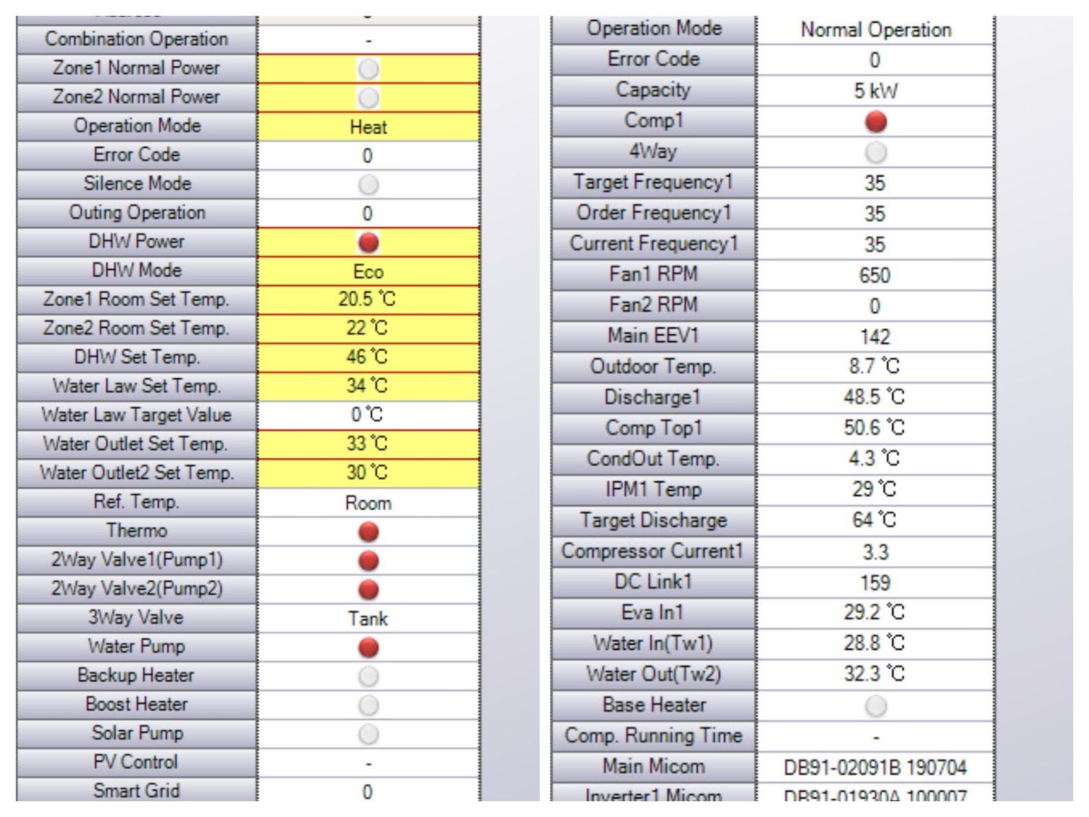
The Engineer was intent on covering the statistics , controls and tests from my wandering gaze!.

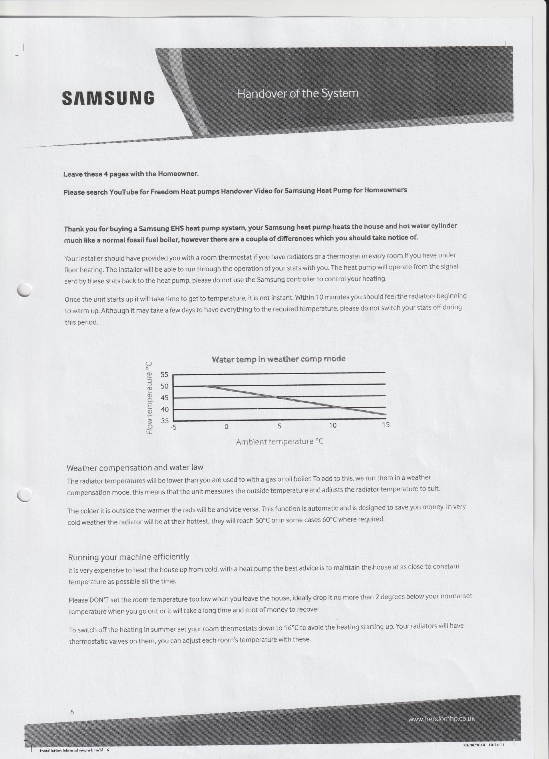
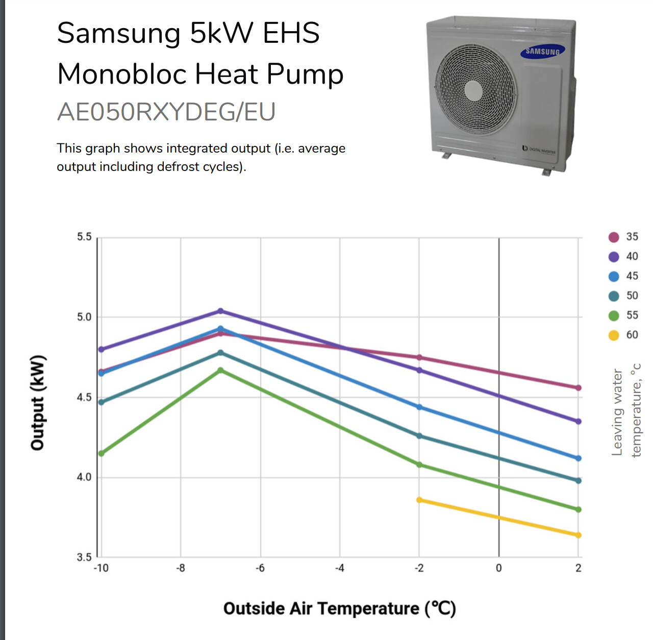
The Power output improved at -7 C exactly corresponding to your graph.

The great advantage of the software hidden by the Samsung engineer was the ability to change a field setting and see the effects , and side effects!


I will have to fit a SonTex 789 . to stop the Endless disputes with my “installer” about the performance of the Heat Pump.

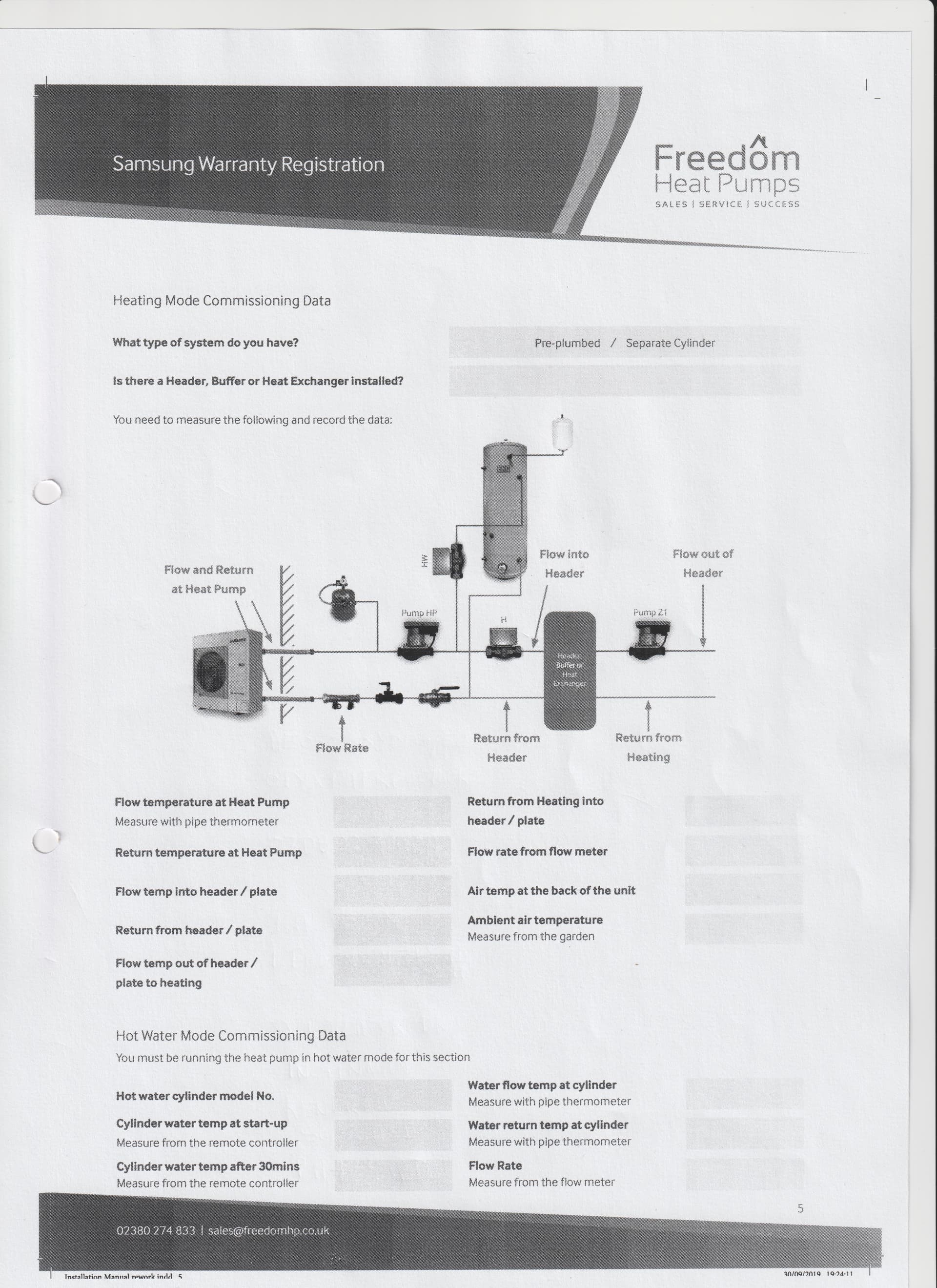
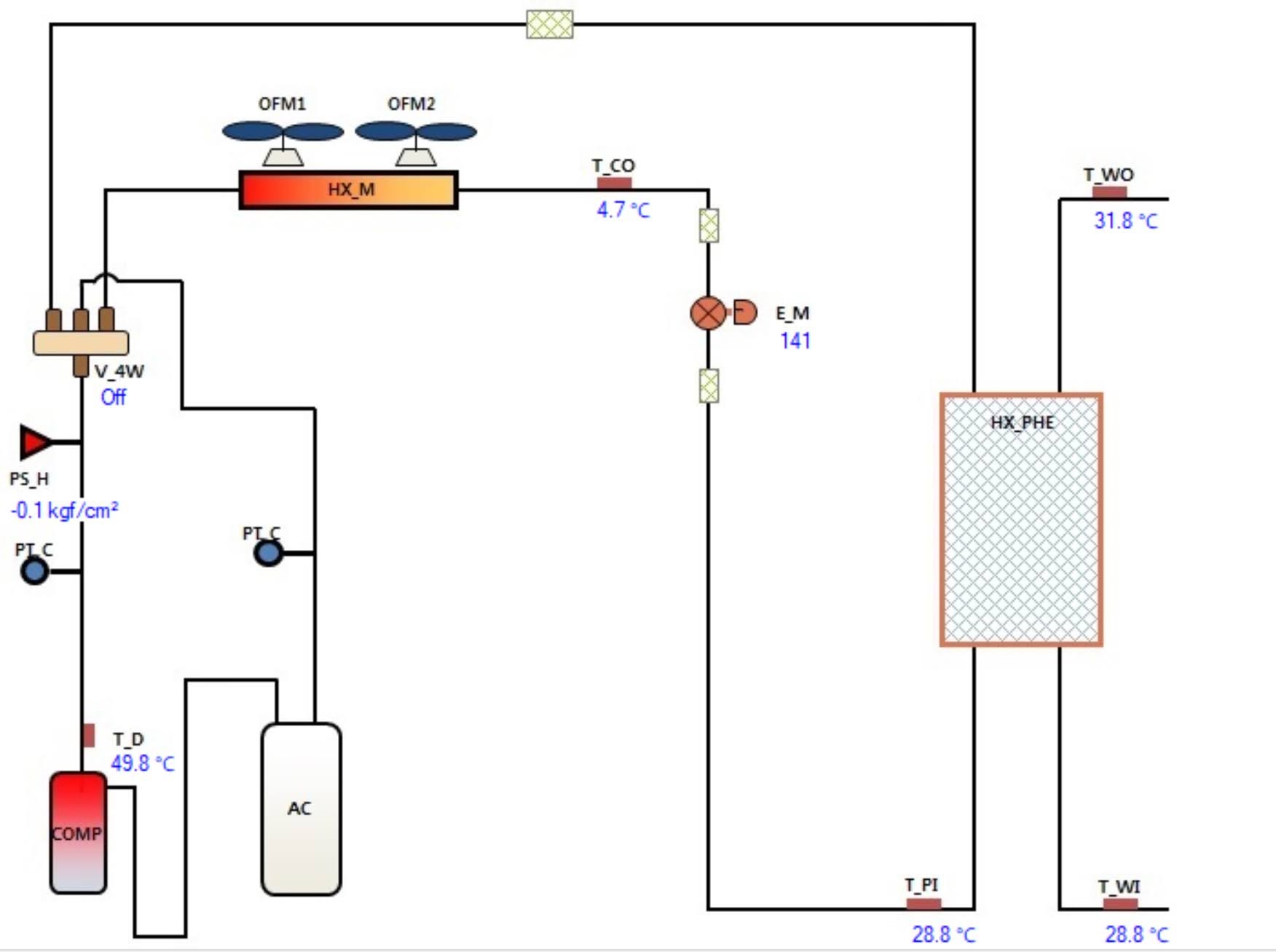
The Performance of a Heat Pump should ONLY be measured from the input power KW and the output power into the Radiator circuit.

Any other measurement leads to the endless dispute scenario , where Hot Water ,De-icing , Heat exchanger, pipes et al are disputed!

I will see if I can afford the USB however, Many thanks Glyn


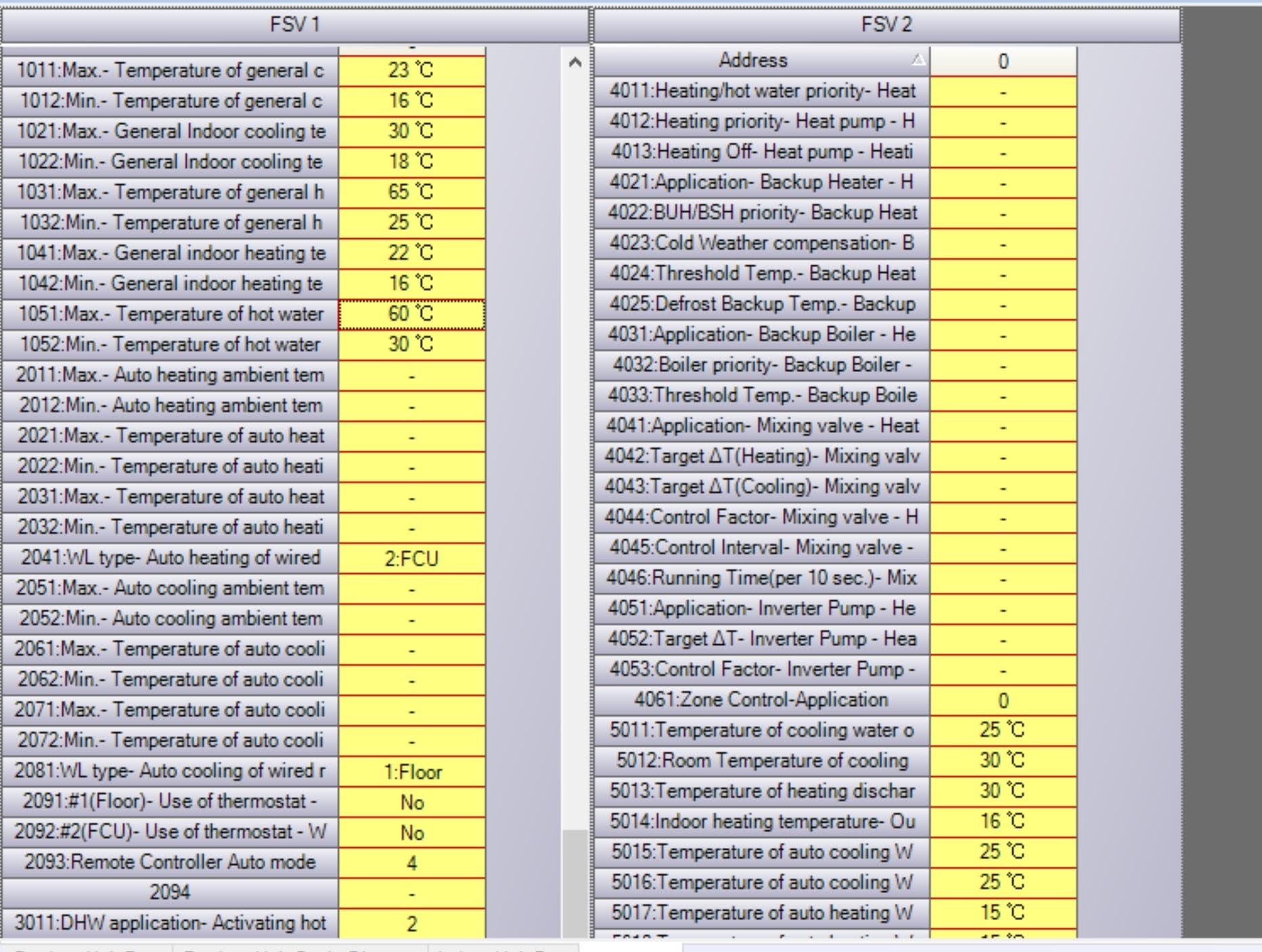
My Visiting Samsung engineer revealed that “he did not understand the the 2091 Field bit settings with options 1 to 4” !

He agreed that the original manuals were written in Korean, being subsequently "machine translated " into a host of other languages!

Specifically, the Samsung engineer did not totally understand the “logic” of the interaction of the Water Law Thermostat with the room Thermostat.

The 2091 options 2,3 and 4 added to the confusion in that the motor pulse controls appeared to be insignificant in practice!.

The Samsung engineer did however confirm that the 2091 Field bits control both the motors and the Two Thermostats, the Room Thermostat and the Water Law thermostat.

Running a Samsung without enabling Weather compensation ( 2091 option 1,2,3 or 4) using Water Law controls and Field bit 2091 is recommended to save between 7 and 10% in Electricity consumption.

ian

Hi Mike,

Again mike, many thanks for your advice, it is appreciated.

The Heat Exchanger was installed to isolate the Heat Pump from the "hydraulic changes on the Radiator circuit.

The Heat pump arrived complete with a pre-fitted Heat Exchanger.

The Heat exchanger cut the original single loop into two isolated water circuits.

The primary water circuit between the heat pump and the heat exchanger only contained 6 litres of water.

With only 6 litres of water in the primary circuit the Heat produced two problems.

"Short Cycling "
With only 6 litres of water in the primary circuit the heat pump began controlling the refrigeration power using mark to space ratio control when operating at the bottom of the Control curve, 25% of maximum power.

The MCS recommended the installation of a volumiser tank . I calculated a volume of 35 Litres following the MCS example calculations.

Samsung, when asked for their opinion , said that a volumiser tank “would also be needed to allow the Heat Exchanger to complete it’s DE-icing cycle.”

Following a recommendation from Kensa , the 50 litre volumising tank was installed “in parallel” with the heat exchanger.

Everybody warned that the volumiser would lower the efficiency since the Energy stored in the Volumising tank

Energy stored in Volumising tank = Tank volume X max Temperature of Water X 4.3 KJ

Here Energy in Volumising tank = 9675 KJ

The Volumising tank was fitted with a switch to disconnect the volumising tank .

When I am frost free and operating away from the bottom of the control curve, (an outside temperature of +15 +/- 2 C when the Heat Pump is in Weather Compensation mode ) I can safely disconnect the volumising tank saving millipennies!

ian